Свяжитесь с Zhouxiang


Обновлено в мае 2026 года. Проверено инженерной командой по сварочным системам ZX.
Неразрушающий контроль сварных швов — это проверка готового соединения на трещины, пористость, несплавления и другие дефекты без механической обработки, травления или разрушения детали. Каждое соответствующее нормам изделие — сосуд под давлением, трубопровод или металлоконструкция — проходит такую проверку и получает подтверждение приёмки. В этом руководстве рассматриваются пять основных методов контроля сварных швов, одобренных AWS: радиографический (RT), ультразвуковой (UT), магнитопорошковый (MT), капиллярный (PT) и визуальный (VT), а также развивающееся применение AI-визуального контроля, связанные с каждым методом стандарты и четыре ключевых вопроса, которые следует задать при выборе метода.Краткие характеристики: пять методов НК
| Метод | Выявляемые дефекты | Поверхностные / подповерхностные | Основной стандарт |
|---|---|---|---|
| VT — визуальный контроль | Трещины, подрезы, профиль, размеры | Только на поверхности | AWS D1.1 § 6, AWS B1.11 |
| RT — радиографический контроль | Поры, шлак, несплавления (объёмные дефекты) | Подповерхностные (объёмные дефекты) | ASME BPVC, разд. V, ст. 2, ISO 17636 |
| UT / PAUT — ультразвуковой контроль | Плоскостные трещины, несплавления, непровары | Поверхностные, приповерхностные, подповерхностные | ASME BPVC, разд. V, ст. 4, ISO 17640 |
| MT — магнитопорошковый контроль | Поверхностные и неглубокие подповерхностные трещины | Поверхность + ~3 мм | ASTM E709, ISO 17638 |
| PT — капиллярный контроль | Выходящие на поверхность трещины, микропоры, утечки | Только на поверхности | ASTM E165, ISO 3452 |
Источник: страницы методов ASNT, AWS B1.10M/B1.10:2016, ASME BPVC Section V (издание 2025 года).
Что такое неразрушающий контроль сварных швов? Пять методов (и почему начинают с VT)
 НК — это набор методов контроля, позволяющих выявлять дефекты сварного шва без повреждения или изменения детали. Методы варьируются от осмотра, который сертифицированный инспектор по сварке проводит с фонарём и измерителем сварных швов, до ультразвуковых систем с фазированной решёткой и кодированием, установленных на роботизированном гусеничном носителе.
«Пять методов», которые изучает большинство сварщиков
От курса по основам НК American Welding Society до руководства AWS B1.10M/B1.10:2016 по неразрушающему контролю сварных швов — в большинстве критериев приёмки по нормам неизменно фигурируют пять основных методов: визуальный (VT), капиллярный (PT), магнитопорошковый (MT), радиографический (RT) и ультразвуковой (UT) контроль. Во многих учебных планах для аттестации CWI эти методы перечислены в разделе обязательных знаний. Число «пять» удобно для повседневных вопросов, однако оно не охватывает все методы. American Society for Nondestructive Testing (ASNT) признаёт в серии своих справочников 16 методов НК, включая вихретоковый контроль (ET), акустическую эмиссию (AE), тепловой и инфракрасный контроль, контроль герметичности и несколько других методов для мониторинга оборудования в эксплуатации. При контроле сварных швов чаще всего применяют пять перечисленных методов, хотя зрелая программа НК при необходимости учитывает и шестой.Почему визуальный контроль всегда проводят первым
В AWS D1.1 — норме по сварке металлоконструкций — прямо указано: «Сварные швы, подлежащие неразрушающему контролю, должны быть признаны годными по результатам визуального осмотра». Швы меньше или больше заданного размера? Их не проверяют рентгеном. Швы деформированы? Ультразвук или поперечная волна не помогут подтвердить их соответствие требованиям. На практике всегда сначала проводят визуальный контроль. Нельзя просто поставить источник излучения и отправить плёнку в лабораторию, если сварной шов деформирован, пока не убедитесь, что с остальным всё в порядке.«Визуальный контроль — основа всех методов НК, поскольку для каждого из них требуется визуальная интерпретация. При большинстве методов НК инспектор использует приборы для проведения проверки. При визуальном контроле сам инспектор выступает в роли прибора, оценивающего деталь». — Bruce Crouse, специалист ASNT VT Level III
Какие существуют 5 видов неразрушающего контроля?
При контроле сварных швов пять основных методов выявляют следующие группы несплошностей:- Дефекты профиля поверхности: трещины, подрезы, наплывы, несплавления в корневом проходе, избыточный размер шва.
- Несплошности, выходящие на поверхность: микропоры или холодные спаи, выявляемые капиллярным контролем, пути утечки.
- Поверхностные и приповерхностные несплошности: продольные трещины, несплавления по границе сплавления в ферромагнитном металле.
- RT выявляет объёмные несплошности внутри сварного шва, например поры, шлаковые включения и несплавления.
- UT и PAUT выявляют плоскостные дефекты (трещины, несплавления, непровары) по всей толщине шва и позволяют измерить их размер и глубину.
Радиографический контроль (RT): рентгеновское и гамма-излучение
 При радиографическом контроле (RT) через сварное соединение пропускают ионизирующее излучение и получают изображение на плёнке, фосфорной пластине для компьютерной радиографии или цифровом плоскопанельном детекторе. Несплошности видны на радиограмме как более тёмные участки, поскольку они лучше пропускают излучение. RT часто называют «рентгеновским контролем», хотя здесь уместнее более общий термин — объёмный контроль сварного шва.
Рентгеновское или гамма-излучение: что выбрать
В промышленном RT используют два типа источников:- Рентгеновские трубки оснащены регулятором VS для настройки напряжения в зависимости от толщины стенки. Их используют в стационарных цеховых условиях для контроля более тонкой стали (примерно до 50 мм, в зависимости от мощности трубки).
- Источники гамма-излучения — это герметичные радиоизотопы, которые постоянно излучают без внешнего питания. Iridium-192 обычно применяют для стали толщиной примерно от 6 мм до 75 мм, а Cobalt-60 используют для очень толстых сечений (более 50-75 мм) благодаря более высокой энергии фотонов.
📐 Примечание для инженеров — IQI / пенетраметры
Чувствительность определяют с помощью индикатора качества изображения (IQI), размещённого на пути излучения. Отверстия в IQI такого типа выполнены в виде трёх отверстий, просверленных в плоской пластине: чувствительность определяется по наименьшему различимому отверстию. Проволочный IQI представляет собой ряд проволок постепенно уменьшающегося диаметра; оценку определяют по самой тонкой проволоке, видимой на радиограмме.
В ASME BPVC Section V Article 2 описаны конструкция IQI и минимальная чувствительность (обычно 2-2T или эквивалентное значение), которую должна обеспечивать радиограмма.Сильные стороны RT и его ограничения
RT особенно эффективен для обнаружения рассеянных пор и шлаковых включений. Он также даёт постоянную запись на плёнке, которую можно хранить после завершения работ. Это важное практическое преимущество, если контракт требует вести архив радиограмм. При этом для интерпретации нужен опытный специалист, а изображение показывает всю толщину стенки целиком. Это может привести к завышенной оценке пористости (на снимке будут видны все пустоты, если пористость из Table One фактически распределена по всей толщине). RT плохо выявляет плоскостные дефекты, ориентированные вдоль плёнки, например расслоения или плотные линии несплавления. (Именно это ограничение в конечном итоге привело к тому, что нормы разрешили применять ультразвуковые методы.)⚠️ Радиационная безопасность
Гамма-радиография регулируется 10 CFR Part 34 (NRC) и соглашениями о взаимном признании со штатами. Установление запретных зон, использование дозиметрических комплектов и наличие квалификации у радиографистов не подлежат обсуждению. Подавляющее большинство цехов при любых обстоятельствах запрещает одновременно вести сварку в запретной зоне. Именно поэтому ультразвуковой контроль стал таким популярным на производственных линиях, которые не могут останавливаться.
Ультразвуковой контроль (UT) и контроль фазированными решётками (PAUT)
 Сварные швы проверяют ультразвуковым методом. Пьезоэлектрический преобразователь вводит в соединение высокочастотный звук (обычно 2-5 МГц для шва из углеродистой стали). Прибор регистрирует эхо-сигналы от внутренних отражателей, электронный временной контур анализирует возвращённую энергию и отображает глубину и амплитуду на экране A-scan, B-scan или C-scan.
Приборы UT позволяют на одном экране выявлять поверхностные, приповерхностные и глубинные дефекты.
Сварные швы проверяют ультразвуковым методом. Пьезоэлектрический преобразователь вводит в соединение высокочастотный звук (обычно 2-5 МГц для шва из углеродистой стали). Прибор регистрирует эхо-сигналы от внутренних отражателей, электронный временной контур анализирует возвращённую энергию и отображает глубину и амплитуду на экране A-scan, B-scan или C-scan.
Приборы UT позволяют на одном экране выявлять поверхностные, приповерхностные и глубинные дефекты.
Обычный UT, фазированная решётка и TOFD
В современной практике контроля сварных швов распространены три варианта:- При традиционном эхо-импульсном UT используется один преобразователь для передачи и приёма сигнала. Оператор вручную перемещает его по поверхности, нанося между преобразователем и металлом контактный гель. Метод недорогой и портативный, но требует высокого мастерства.
- Преобразователь PAUT состоит из 16-128 небольших элементов. Их активируют группами с точно заданными временными задержками, электронно управляя углом и фокусировкой луча. За один проход сканируется всё поперечное сечение сварного шва, а данные сохраняются в файл. Позже инспектор может изучить запись.
- При TOFD (дифракционно-временном методе) пара преобразователей, один из которых передаёт сигнал, а другой принимает, измеряет дифракцию на вершинах трещин. Этот метод очень точно определяет высоту дефекта по толщине стенки и обычно применяется вместе с PAUT, если используют методику измерения высоты дефекта.
Результаты UT дают полезную информацию для планирования ремонта и замены оборудования и механизмов. Сегодня широко применяются как обычные, так и усовершенствованные методы UT, поэтому для специалистов по НК особенно важны актуальная квалификация и сертификация. — Huidong Gao, специалист ASNT UT Level III
Может ли UT с фазированной решёткой заменить радиографический контроль?
Да, во всё большем числе случаев, предусмотренных нормами. В рецензируемой статье ASME «Обзор ультразвуковых фазированных решёток для контроля сосудов под давлением и трубопроводов» подробно описано, как новые нормы для сосудов под давлением — в особенности ASME Code Case 2235 — разрешили применять PAUT вместо RT для контроля сварных швов таких сосудов. С 2010 года в основной текст ASME Section V Article 4 включены положения об использовании UT для контроля сварных швов, поэтому во многих случаях больше не требуется специальное разрешение. В API 620 и API 650 есть Appendix U с подробным описанием применения ультразвукового контроля вместо RT. United States Nuclear Regulatory Commission также разрешила использовать PAUT вместо RT для трубопроводов, связанных с безопасностью, на таких объектах, как электростанция Turkey Point компании Florida Power & Light, согласно документу ML17208A058. Практические преимущества: не требуется радиационная защита, данные хранятся в электронном виде, а не на плёнке, можно измерять размер дефектов по толщине стенки, сварщик сразу получает обратную связь. Сообщество Reddit r/nondestructivetesting подтверждает это простыми словами: один специалист считает, что у RT остались такие преимущества, как «постоянная запись изображений и менее субъективная интерпретация», а сканеры PAUT уже стали «отраслевым стандартом» на многих проектах трубопроводов.⚠️ Типичная ошибка — операторы PAUT без основ работы с поперечной волной
В ходе обсуждения на форуме общего курса ACA затрагивалось несколько тем. В частности, постоянно упоминался распространённый недостаток у сертифицированных инспекторов: специалисты по PAUT часто не имеют практического опыта обычного ультразвукового контроля поперечной волной. Интерпретировать изображение S-scan непросто: на него может влиять преобразование мод, вызванное геометрией детали, или плохой акустический контакт с поверхностью. Простое решение, которое, похоже, работает: прежде чем переходить к новым инструментам сканирования, необходимо освоить обычный UT.
✔ Преимущества UT / PAUT
- Нет радиационной опасности и необходимости создавать запретную зону
- Лучше RT выявляет плоскостные дефекты (LOF, LOP)
- Электронный архив данных, не нужно работать с плёнкой
- Результаты доступны сразу — сварщик может устранить дефект в ту же смену.
- Измерение высоты дефекта по толщине стенки для оценки пригодности к эксплуатации
⚠ Ограничения UT / PAUT
- Нужен контактный материал — гель или вода при каждом контакте
- В крупнозернистых материалах (литой нержавеющей стали) звук рассеивается
- Мёртвая зона у поверхности при эхо-импульсном контроле
- Стоимость PAUT: $30 000–$100 000+ за прибор, не считая энкодера и сканера
- Требования к обучению выше, чем для RT или PT
Магнитопорошковый контроль (MT / MPI)
 Магнитопорошковый контроль выявляет поверхностные и приповерхностные несплошности в ферромагнитных материалах — углеродистой стали, низколегированных сталях, ферритной нержавеющей стали. Для этого создают магнитное поле и наносят частицы оксида железа. Если дефект нарушает магнитное поле, возникающий поток рассеяния собирает частицы в видимую индикацию, повторяющую форму дефекта.
Как создаётся магнитное поле
При контроле сварных швов используют два основных способа создания магнитного поля. Переносной электромагнитный ярмовой прибор устанавливают по обе стороны шва; он создаёт продольное поле между полюсами. Щупы пропускают через деталь постоянный ток, создавая круговое поле. Направление поля может иметь решающее значение: трещина даёт индикацию, только если расположена под углом к силовым линиям. Поэтому по требованиям ASTM E709 и ISO 17638 необходимо поворачивать прибор на 90 градусов.Сухой или мокрый способ, видимые или флуоресцентные частицы
Частицы наносят сухим способом (цветной порошок распыляют из груши) или мокрым (частицы взвешены в керосине или воде). На шероховатых поверхностях после сварки сухие частицы работают лучше мокрых; мокрые частицы мельче и выявляют более тонкие трещины. Флуоресцентные частицы проверяют в ультрафиолетовом свете: чувствительность при этом выше, чем у частиц, видимых при обычном освещении. Поэтому в аэрокосмической промышленности для контроля компонентов двигателей обычно применяют мокрый флуоресцентный MT.💡 Совет специалиста — проверка ферромагнитности
Перед снятием ярмового прибора проверьте шов ручным магнитом. Если магнит не притягивается, MT будет неэффективен. Аустенитную нержавеющую сталь (304, 316, дуплексный основной металл с аустенитным присадочным материалом) и алюминиевые сварные швы магнит не притягивает. Вместо этого проведите PT или используйте объёмные методы. Если применить MT к немагнитному шву и сообщить об «отсутствии индикаций», это приведёт к ложноотрицательному результату — классическому признаку неподготовленного инспектора во время аудита.
Капиллярный контроль (PT) с применением пенетранта
 Капиллярный контроль выявляет выходящие на поверхность дефекты во всех непористых материалах: стали, нержавеющей стали, алюминии, меди, титане, а также стекле и керамике. Если магнитопорошковым методом нельзя проверить шов из нержавеющей стали, применяют PT.
Пять этапов PT по ASTM E165
- Предварительная очистка: обезжирьте и высушите сварной шов — масло, остатки шлака и краска препятствуют проникновению пенетранта.
- Нанесение пенетранта: распылите, окуните или нанесите кистью контрастный либо флуоресцентный краситель на поверхность сварного шва.
- Выдержка: оставьте пенетрант на требуемое время — обычно 5-30 минут для сварных швов по ASTM E165; для тонких усталостных трещин требуется больше времени.
- Удаление излишков: очистите поверхность средством, указанным производителем пенетранта (водой, растворителем или эмульгатором). Не заливайте поверхность: так краситель вымоется из трещин.
- Нанесение проявителя и осмотр: нанесите порошковый проявитель; он вытянет краситель из дефектов и сделает индикацию заметнее. Индикации видимого красителя осматривают при белом свете; для флуоресцентного красителя нужен источник UV-A.
📐 Примечание для инженеров — температура поверхности
PT остаётся недорогим (базовый комплект из трёх аэрозольных баллончиков стоит меньше $50), портативным и подходит для поверхностей разной геометрии: его можно применить к угловому шву, Т-образному соединению труб или даже к потолочному шву, который, казалось бы, проще не делать. Недостаток метода существенный: он выявляет только дефекты, выходящие на поверхность. Несплавление под поверхностью на глубине 2 мм ниже усиления шва не будет видно, сколько бы вы ни ждали.
ASTM E165 допускает температуру детали от 50F до 125F (10C до 52C) при проведении процедуры. При температуре ниже нижнего предела вязкость пенетранта повышается, он хуже проникает капиллярным способом в тонкие трещины — на первый взгляд швы выглядят чистыми, хотя в них есть тонкие трещины. Для контроля PT в холодную погоду требуется аттестованная низкотемпературная процедура с увеличенной выдержкой или другой химией пенетранта.
AI-визуальный контроль: применение машинного зрения при НК сварных швов
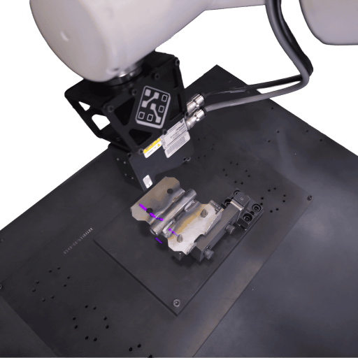
Об этом разделе. AI-визуальный контроль сварных швов — новая технология на быстро меняющемся рынке поставщиков. Приведённые ниже описания основаны на материалах коммерческих продуктов и недавних академических исследованиях; заявленные показатели точности сильно различаются в зависимости от обучающих данных, класса дефектов и основного материала, а AWS и ASME пока не опубликовали документов, в которых AI-зрение позиционировалось бы как замена сертифицированному инспектору по сварке.
При AI-визуальном контроле сварных швов к изображениям поверхности шва применяются свёрточные нейронные сети — то же семейство архитектур компьютерного зрения, которое используют в роботах и радиологии. Камера, часто дополненная профилометрией со структурированным светом или лазерной линией, снимает сформированный сварной шов; модель классифицирует его геометрию как допустимую или относящуюся к одной из нескольких категорий дефектов (пористость, подрез, брызги, пропущенный шов, неровный профиль усиления).
Что замечает AI-зрение, но пропускает человек при визуальном контроле VT
Поставщики делают ставку на стабильность результатов, а не на чудеса машинного зрения. Обученная модель проверяет каждый валик на роботизированной сварочной ячейке по единому критерию, не устаёт в середине смены и сохраняет изображения каждого сварного шва с отметкой времени для последующего контроля. Системы прогнозирования также передают данные о форме валика обратно в контроллер сварки, чтобы скорректировать напряжение, подачу проволоки или скорость перемещения. Инвесторы проявляют большой интерес — венчурные инвестиции активно поступают в этот сектор. Большинство коммерческих поставщиков демонстрируют на своих типовых примерах обнаружение дефектов по всей длине шва с точностью более 90 процентов; инвестиции продолжались и в 2024 и 2025 годах.Что ИИ не может заменить
AI-камера не создаёт в сварном шве магнитное поле, не пропускает через него звук и не формирует рентгенограмму. С точки зрения физики это визуальный метод с теми же ограничениями, что и визуальный контроль VT человеком: он охватывает только поверхность. AWS D1.1 по-прежнему требует, чтобы визуальный контроль выполнял квалифицированный специалист, а приёмку с присвоением клейма по нормам проводит человек, а не AI-система. Практичное размещение камеры — лишь дополнение: AI-визуальный контроль обеспечивает 100 % контроль сварных швов в ходе производства, а инспекторы по сварке CWI и объёмные методы (RT/UT) проводят приёмочный контроль, обязательный по нормам.Интеграция в роботизированные сварочные ячейки
Одно из оптимальных применений AI-визуального контроля — внутри роботизированной сварочной ячейки. Камера на отдельном неподвижном манипуляторе или на манипуляторе со сварочной горелкой одновременно снимает каждый шов в зоне контроля сразу после сварки, пока деталь остаётся зажатой в сварочном приспособлении и неправильно расположенный шов ещё можно исправить, не выгружая и не загружая деталь заново. Это преимущество особенно важно в роботизированных сварочных ячейках для изготовления сосудов под давлением для энергетической отрасли, где по контракту требуется 100 % контроль и где стоимость пропущенного дефекта (возврат сосуда, повторное испытание по нормам) намного превышает капитальные затраты на камеру и соответствующее программное обеспечение.Как выбрать метод: охват дефектов, стоимость и скорость
 Выбор подходящего метода — это не поиск решения, которое в демонстрационном видео рекламодателя показывает наилучшее сочетание чувствительности и специфичности. Нужно выбрать метод, который надёжно выявляет те классы дефектов, которые регулируются применимым кодом, с учётом имеющихся материалов и ограничений проекта по радиационной безопасности, подготовке специалистов и бюджету. Обычно команде помогают принять правильное решение две таблицы и оценка по четырём вопросам.
Матрица выявления дефектов разными методами
| Дефект | VT | PT | MT | RT | UT / PAUT |
|---|---|---|---|---|---|
| Поверхностная трещина | ограниченно | ✔ | ✔ | ограниченно | ✔ |
| Подповерхностная трещина | ✘ | ✘ | ~3 мм | ограниченно | ✔ |
| Пористость | только на поверхности | только на поверхности | только на поверхности | ✔ | ограниченно |
| Шлаковое включение | ✘ | ✘ | ✘ | ✔ | ✔ |
| Несплавление (LOF) | ✘ | ✘ | только на поверхности | ограниченно | ✔ |
| Непровар (LOP) | только в корне шва | только в корне шва | только в корне шва | ✔ | ✔ |
| Подрез | ✔ | ✘ | ✘ | ✘ | ✘ |
| Расслоение (параллельно поверхности) | ✘ | ✘ | ✘ | ограниченно | ✔ |
Какой метод НК лучше всего подходит для выявления поверхностных трещин?
Для трещин, выходящих только на поверхность, выбор зависит от основного материала. Для ферромагнитной стали используйте MT: ярмо с сухим порошком даст чёткую индикацию менее чем за минуту. Для нержавеющей стали или алюминия используйте PT: магнитное поле не будет взаимодействовать с немагнитным сплавом. Для узких усталостных трещин, которые не видны при цветной капиллярной дефектоскопии, хорошо подходит флуоресцентный PT под ультрафиолетом. UT также выявляет поверхностные трещины, но для проверки поверхности на реальные, а не искусственно созданные дефекты этот метод избыточен по сравнению с MT или PT, а необходимый уровень квалификации оператора сложнее обосновать.Как выбрать метод НК: 4 вопроса
Задавайте вопросы по порядку. Каждый ответ сужает выбор метода.
- Нужно проверить только поверхность или весь объём? Для поверхности используйте VT/PT/MT. Для контроля объёма нужны RT или UT/PAUT.
- Материал ферромагнитный? Если да, MT быстрее PT при проверке поверхности. Если нет (аустенитная нержавеющая сталь, алюминий, медь, титан), используйте PT.
- Требуют ли код или контракт постоянную запись результатов? Если требуется плёнка, RT остаётся самым простым вариантом. Если допустима электронная запись, используйте PAUT с закодированными данными.
- Допускает ли рабочая зона радиационное обследование или главным ограничением является скорость всей производственной линии? Если радиационное обследование невозможно или важна скорость, используйте PAUT (или машинное зрение на базе AI для выявления дефектов вне экрана). Если радиационное обследование допустимо и нужна разовая проверка, подойдёт RT.
Для большинства сосудов под давлением и трубопроводов, изготовленных по API 650, ASME B 31.3 и ANSI B16.5, применяемые нормы всегда предусматривают VT и один из двух методов контроля объёма. Для тонкостенных труб теплообменников предусмотрены VT и PT. Это отправная точка, а не замена соответствующего положения вашего кода.
Коды, стандарты и критерии приемки
 Область применения каждого метода НК показывает, что он может выявить. Коды определяют требования вашей отрасли. Большинство проектов подпадает под действие одного из пяти основных нормативных документов.
| Код / стандарт | Область применения | Методы НК |
|---|---|---|
| AWS D1.1 / D1.1M | Кодекс по сварке металлоконструкций — сталь | VT (обязателен), PT, MT, RT, UT |
| Раздел V ASME BPVC | Кодекс для котлов и сосудов под давлением — методы неразрушающего контроля | Все пять (статья 4 охватывает UT, включая PAUT, с 2010 года) |
| Раздел IX ASME BPVC | Квалификация по сварке, пайке и сварке плавлением | VT, а также методы Section V, на которые приводятся ссылки |
| API 1104 | Сварка трубопроводов и связанных с ними объектов | VT, RT, автоматизированный UT (AUT/PAUT), MT, PT |
| ISO 17636 / 17640 / 17638 / 3452 | Международные аналоги для RT, UT, MT, PT | Каждый стандарт ISO охватывает один метод |
| ASTM E165, E709 | Стандартные методики для PT и MT | PT (E165), MT (E709) |
Сертификация инспекторов
В этой сфере преобладают две системы сертификации. Квалификация AWS Certified Welding Inspector (CWI) подтверждает подготовку специалиста по визуальному контролю в соответствии с AWS D1.1 и аналогичными кодами; экзамен охватывает способы сварки, обучение требованиям кодов и практику инспекции. ASNT SNT-TC-1A — это рекомендуемая практика, на основе которой работодатели аттестуют инспекторов уровней I, II и III по каждому отдельному методу НК. Для большинства проектов с сосудами под давлением и трубопроводами требуются оба специалиста: инспектор по визуальному контролю с квалификацией CWI и специалист по НК уровня II или III.Перспективы отрасли: НК при роботизированной сварке и дальнейшее развитие машинного зрения на базе AI
 Согласно собственному отчёту MarketsandMarkets о рынке НК и инспекционного контроля за 2025 год, объём мирового рынка неразрушающего контроля и инспекций в 2025 году составит USD 14,99 млрд, а к 2030 году вырастет до USD 22,34 млрд при среднегодовом темпе 8.3 процента. Для сварочной отрасли особенно важны три тенденции.
PAUT продолжает вытеснять RT при изготовлении оборудования по требованиям кодов
Изменения в стандартах в основном уже завершены: ASME Section V Article 4 напрямую предусматривает UT сварных швов с 2010 года, процедура Code Case отработана, API 620 и 650 содержат Appendix U, а NRC разрешила применять PAUT вместо RT для ответственных трубопроводов на многих предприятиях США. Дальнейшие изменения происходят у производителей, особенно при изготовлении трубных узлов и продольных швов сосудов под давлением, где сканеры PAUT уже входят в стандартное оснащение. Если в 2026 году и позднее вы выбираете производителя, предусмотрите приём файлов PAUT с закодированными данными вместо организации зон радиационного контроля.Машинное зрение на базе AI переходит от отбраковки к управлению с обратной связью
На первом этапе система выявляла дефект сварного шва уже после его появления. На втором этапе, который некоторые пользователи уже внедрили в производство, параметры формы валика в режиме реального времени передаются обратно контроллеру сварки. Тот изменяет напряжение, скорость подачи проволоки или скорость перемещения горелки, прежде чем пограничное по качеству соединение будет забраковано. Так закономерно развивается поточный контроль в системах роботизированной сварки, разработанных для сварных соединений энергетического оборудования, отвечающих требованиям кодов: контур контроля обеспечивает соответствие требованиям ASME, а контур управления поддерживает производительность.Контроль без вскрытия (NII) сокращает число работ в замкнутом пространстве
Одновременно растёт применение NII при обследовании судов в эксплуатации: используют PAUT, ультразвуковой контроль с направленными волнами и термографию. Если проводить работы, не вскрывая конструкцию, можно обойтись без строительных лесов, дегазации и разрешений на работы в замкнутом пространстве. По отзывам специалистов на r/nondestructive testing, это подтверждает тенденцию, о которой сообщают подразделения, отвечающие за целостность оборудования: клиенты действительно запрашивают предложения по NII вместо обследований, требующих входа в замкнутое пространство (CSE). Владельцам сварных конструкций необходимо предусмотреть возможности проведения PAUT в цехе, а также UT на этапе сборки.Производителям, планирующим капитальные затраты на 2026 год: если объём сварочных работ ограничен требованиями ASME Section V, AWS D1.1 или API 1104, наиболее востребованное вложение в НК — оценка целесообразности применения PAUT с закодированными данными и оптическим контролем на базе AI в качестве фильтра на производственной линии перед ним. RT по-прежнему подходит для отдельных нестандартных изделий с большой толщиной стенки, но отрасль уже движется дальше:
Часто задаваемые вопросы
В: Что такое неразрушающий метод оценки сварного соединения?
Посмотреть ответ
Неразрушающий контроль. Это проверка сварного соединения на наличие дефектов без разрушения, разрезания, разлома или повреждения соединения. Согласно AWS B1.10M/B1.10:2016, к пяти наиболее распространённым методам относятся визуальный, капиллярный, магнитопорошковый, радиографический и ультразвуковой контроль.
В: Как проводят НК сварного шва?
Посмотреть ответ
Сначала квалифицированный специалист проводит визуальный контроль; AWS D1.1 требует, чтобы перед применением любого другого метода НК сварной шов прошёл как минимум контроль PT/MT. Затем выберите метод, предусмотренный применимым кодом, для выявления нужного дефекта: PT или MT — для поверхностных дефектов, RT или UT — для внутренних дефектов сварного шва. Наконец, зафиксируйте результаты контроля в соответствии с положениями кода.
В: Чем отличаются MT и PT при контроле сварных швов?
Посмотреть ответ
Магнитопорошковый контроль работает только на ферромагнитных материалах, например на углеродистой и ферритной стали, включая ферритную нержавеющую сталь. Он выявляет дефекты на глубине примерно до 3 мм от поверхности. Капиллярный контроль подходит для любых непористых материалов, включая аустенитную нержавеющую сталь и алюминий, но выявляет только дефекты, выходящие на поверхность.
Если магнит притягивается к сварному шву, используйте MT; если нет — PT.
В: Когда для контроля сварных швов следует использовать RT, а когда UT?
Посмотреть ответ
Используйте RT, если по договору требуется постоянная запись на плёнке в формате 2D, условия на площадке допускают создание зоны радиационного контроля или вас больше всего беспокоят пористость от газовых включений и шлаковые включения. Используйте UT или PAUT — с отображением объёма в формате 2D в реальном времени или без него, — если вас беспокоят плоскостные дефекты (непровар, трещины), недопустимо радиационное воздействие, скорость ограничена темпом производственной линии или требуется определить размер дефекта по толщине стенки. Многие действующие нормы — ASME Section V Article 4, API 620 Appendix U, ASME Code Case 2235 — теперь предписывают применять PAUT вместо RT.
В: Насколько точен визуальный контроль сварных швов с помощью AI по сравнению с контролем CWI?
Посмотреть ответ
Большинство заявленных поставщиками показателей точности классификаторов дефектов сварных швов на основе AI находится в верхней части диапазона 90 процентов для узко определённых классов дефектов и материалов основы, однако фактические результаты после установки по-прежнему сильно зависят от обучающих данных и освещения. AI-зрение остаётся очень полезным уровнем контроля на 100 процентов, хорошо подходящим для роботизированных ячеек, но нормы не позволяют использовать его вместо сертифицированного инспектора по сварке, например, в рамках AWS D1.1, или вместо объёмных методов (RT, UT), когда их применение обязательно.
В: Требует ли AWS D1.1 проводить НК каждого сварного шва?
Посмотреть ответ
Нет. AWS D1.1 требует визуально контролировать все сварные швы в области применения кодекса, однако дополнительный НК (PT, MT, RT, UT) нужен только в случаях, указанных в контрактной документации, — обычно для конструкций с циклической нагрузкой, элементов, критичных к разрушению, и сварных швов на растяжение в статически нагруженных конструкциях. Частоту выборочного контроля устанавливает ответственный инженер.
Подбираете роботизированную сварочную ячейку, качество сварных соединений которой должно соответствовать критериям приемки ASME или AWS? Давайте вместе проработаем стратегию контроля и подберём сварочную систему.
Связаться с инженерной командой ZX →О руководстве по НК сварных швов
В этом руководстве за 2026 год собраны описания методов НК сварных швов, сведения о выявляемых дефектах и ссылки на коды из справочников ASNT по методам контроля, AWS B1.10M/B1.10:2016, ASME Section V, стандартов API и научной литературы о замене радиографии методом PAUT. Данные поставщиков о точности визуального контроля на базе AI основаны на их тематических исследованиях и актуальных публикациях. Перед использованием этих данных для определения требований к собственной роботизированной сварочной линии необходимо подтвердить их достоверность.
Ссылки и источники
- Метод визуального контроля (VT) при неразрушающих инспекциях — Американское общество неразрушающего контроля (ASNT)
- Ультразвуковой контроль (UT): PAUT, TOFD и методы НК — Американское общество неразрушающего контроля (ASNT)
- Руководство AWS B1.10M/B1.10:2016 по неразрушающему контролю сварных швов — Американское общество сварки
- Онлайн-курс по основам неразрушающего контроля — Американское общество сварки
- Обзор применения ультразвуковых фазированных решёток для контроля сосудов под давлением и трубопроводов — журнал ASME по технологии сосудов под давлением
- Фазированная решётка UT на АЭС Turkey Point вместо RT (ML17208A058) — Комиссия по ядерному регулированию США
- NUREG/BR-0024: безопасное проведение гамма-радиографии — Комиссия по ядерному регулированию США
- ASTM E165/E165M: стандартная практика капиллярного контроля — ASTM International
- Отчёт о рынке НК и инспекционного контроля за 2025 год — MarketsandMarkets Research
Статьи по теме
- Сварка трубопроводов: критерии приемки API 1104 и порядок контроля методом PAUT
- Расчёт ROI роботизированной сварки: стоимость доработки, контроля и повторных проверок по коду
- Разбор стоимости роботизированной сварочной ячейки, включая оборудование для поточного контроля сварных швов
- Роботизированная и ручная сварка: качество сварных соединений, повторяемость и объём контроля
- Критерии выбора сварочного робота для сосудов под давлением, изготовленных по требованиям кодов
- Введение в технологии роботизированной сварки, НК и интеграцию систем качества