Get in Touch with Zhouxiang

Updated: August 13, 2026
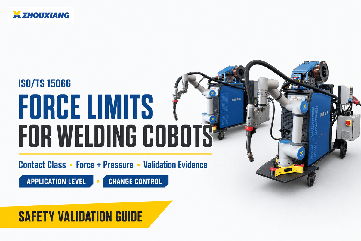
ISO TS 15066 cobot welding safety is not a matter of typing one force number into a robot controller. Defensible welding applications start by identifying every foreseeable contact, classifying the body region and contact type, measuring the applicable force and pressure, and preserving the tested configuration as evidence.
Quick answer
ISO/TS 15066 provides collaborative-application guidance, including biomechanical limits used for power and force limiting. It does not certify a cobot model, replace the application risk assessment, or control arc radiation, fumes, heat, spatter, electricity, sharp workpieces, or trapping created by the cell. If the application assessment calls for presence sensing, safety laser scanners and light curtains from CCH provide product options for review; they do not replace control of welding-specific hazards or validation of the cell.
| Before accepting a contact | Evidence to retain |
|---|---|
| Classify the task and contact | Scenario, body region, transient or quasi-static condition, and contact geometry |
| Select the applicable criteria | Standard edition, project rules, force limit, pressure limit, and assumptions |
| Test the frozen application | Instrument setup, calibration, raw traces, result, corrective action, and approval |
What ISO/TS 15066 Requires, and What It Does Not
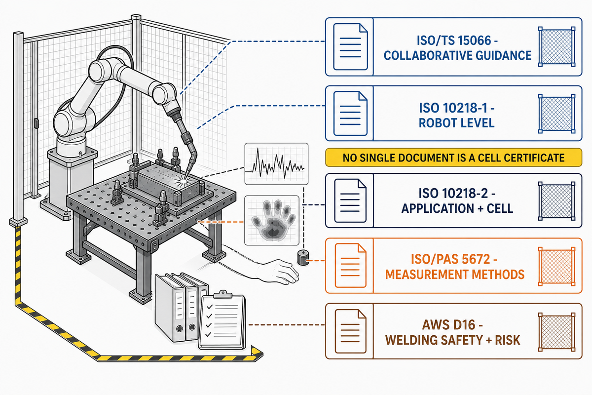
One common application-risk mistake is treating an industrial standard as a product label. ISO’s catalogue entry for ISO/TS 15066:2016 still lists the document as published and current, while its lifecycle stage says it is to be revised. That status does not certify an individual welding cell.
| Document | Practical role in a welding-cobot project | Important boundary |
|---|---|---|
| ISO/TS 15066:2016 | Collaborative robot-system guidance, including power-and-force-limiting contact criteria | Supplements the broader industrial-robot safety framework; not a cell certificate |
| ISO 10218-1:2025 | Robot-level design and information for integration | Robot conformity does not prove the integrated welding application is safe |
| ISO 10218-2:2025 | Application and cell integration, commissioning, use, maintenance, and decommissioning | Exact adopted editions depend on the project and jurisdiction |
| ISO/PAS 5672:2023 | Methods for measuring and analyzing human-robot contact force and pressure | Does not identify which hazards or contact scenarios the risk assessment must select |
| AWS D16.1:2018 and D16.3:2026 | Welding-specific safety and robotic arc-welding risk-assessment references | Use when applicable to the contract or jurisdiction; do not treat a catalogue summary as the normative text |
Status check, not a legal conclusion
The 2025 editions of ISO 10218-1 and ISO 10218-2 were published in February 2025. Confirm the editions named by the purchaser, risk assessor, local regulator, and conformity route before testing.
Within this standards set, the technical specification adds collaborative robot safety guidance while ISO 10218 carries broader safety requirements for industrial robots and their applications. Collaborative operation may also use measures such as a safety-rated monitored stop or speed and separation monitoring; those methods are distinct from power and force limiting, and no cobot safety or safety standard label selects the right method automatically.
Terminology that affects the test
The robot arm, safety functions, end tooling, workpiece, fixture, and human task form one application. That is why industrial-robot application safety cannot be reduced to the arm’s speed and force settings.
Normalize RFQ language before choosing a test
Specifications often mix robot safety standards, product descriptions, and control-language shorthand. Treat the following phrases as prompts to define scope, edition, evidence, and ownership—not as proof that a requirement applies or that safety compliance has already been established.
| Language found in specifications | Question the project must answer |
|---|---|
| “robots and robotic devices,” “industrial robots and their integration,” “collaborative robot application,” “cobot cell,” “6-axis articulated robot,” or “cobot payload” | Which robot, tooling, payload, cell boundary, and human task are actually inside the assessment? |
| “functional safety,” “functional safety requirements,” “safety system,” “safety features,” “robot stopping,” or “robot slows or stops” | Which safety function, operating mode, performance target, validation method, and fault response are required? |
| “safety enclosures,” “safety laser,” “ISO 13855,” or “distance between the robot and a person” | Which access or separation hazard is being controlled, and which edition and measured layout support the decision? |
| “per ISO 12100,” “per ISO 13849-1,” “robot safety standards,” or “safety compliance” | Who confirms applicability, adopted edition, jurisdiction, evidence package, and acceptance authority? |
| “four collaborative operation modes,” “contact with a person,” “contact between the robot and a person,” “guidance for collaborative robot use,” or “Universal Robots” | Is the phrase naming an operating method, a contact scenario, generic equipment, or a specific brand—and what application evidence follows from that distinction? |
7-Node Force-Limit Decision Chain
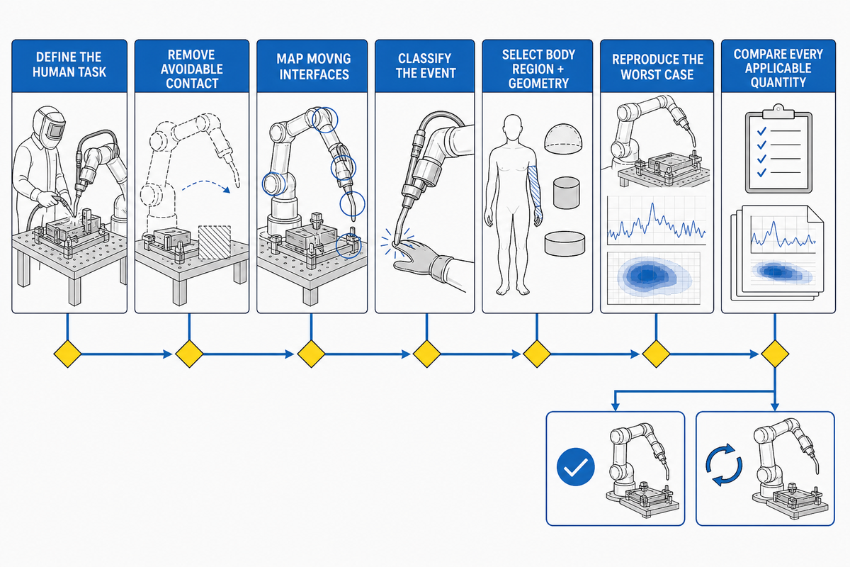
Limits sit at the end of the decision chain, not the beginning. If a team starts with “What force number can we enter?”, it has skipped the questions that determine whether contact is acceptable and which criterion applies.
- Define the human task, including production, loading, teaching, debugging, maintenance, repair, and recalibration.
- Remove avoidable contact by changing the layout, access, fixtures, sequence, or safeguards before trying to justify a contact with a number.
- Identify every moving interface: the arm, torch, wire, cable dress, workpiece, positioner, fixture, and carried part.
- Classify the event by deciding whether the person can recoil from a transient impact or may be trapped in a quasi-static contact.
- Select the body region and geometry because a broad padded surface and a narrow workpiece edge don’t create the same pressure distribution.
- Freeze and reproduce the worst case, recording payload, tool, path, speed, reach, direction, effective mass, fixture, and counter-surface.
- Compare every applicable quantity. Where the selected criteria specify force and pressure, both must pass; otherwise redesign the contact or add safeguarding.
Two-Number Fallacy
Force and pressure values aren’t universal settings for an entire cell. Each value belongs to a defined contact scenario, body region, contact classification, geometry, test configuration, and edition of the applicable criteria.
Pass-Both Rule for Applicable PFL Contacts
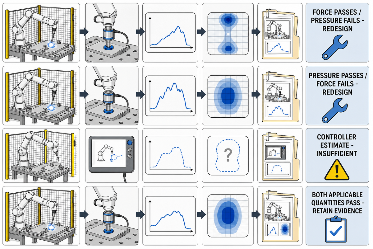
Force describes the overall interaction, while pressure depends heavily on the area and shape over which that force acts. Broad compliant padding can reduce peak pressure without necessarily reducing total force; a narrow torch bracket or workpiece corner can concentrate pressure even when the force reading looks modest.
“As soon as either the force or the pressure limit is exceeded, the requirements are not fulfilled.”
DGUV FB HM-080, guidance for power-and-force-limited robot systems
| Observed result | What it proves | Decision |
|---|---|---|
| Applicable force passes; pressure fails | Energy may be controlled, but geometry still concentrates load | Not accepted; change contact shape, padding, clearance, path, or safeguarding |
| Pressure passes; applicable force fails | Contact is spread out, but total interaction remains excessive | Not accepted; reduce energy, speed, effective mass, or exposure |
| Controller force estimate is below a setting | Only that the controller reported its estimate under that run | Insufficient without scenario-specific contact measurement |
| Both applicable quantities pass | Testing confirmed the contact under the frozen conditions | Retain evidence and continue with all other application hazards |
That qualification matters. NIST’s biomechanical-limits workshop record notes that pain onset can be expressed through quantities such as force or normal stress and that impactor shape affects validity. Apply the pass-both rule where the selected PFL criteria set both limits; do not turn it into an unsupported universal statement.
Copyright and accuracy boundary
This guide does not reproduce the complete ISO/TS 15066 Annex A limit table. Select authoritative values from the licensed standard and the editions adopted for the project; avoid generic claims such as “150 N” or “65 N” without the associated body region and contact conditions.
Classify Every Contact With a Contact-Map Test Matrix
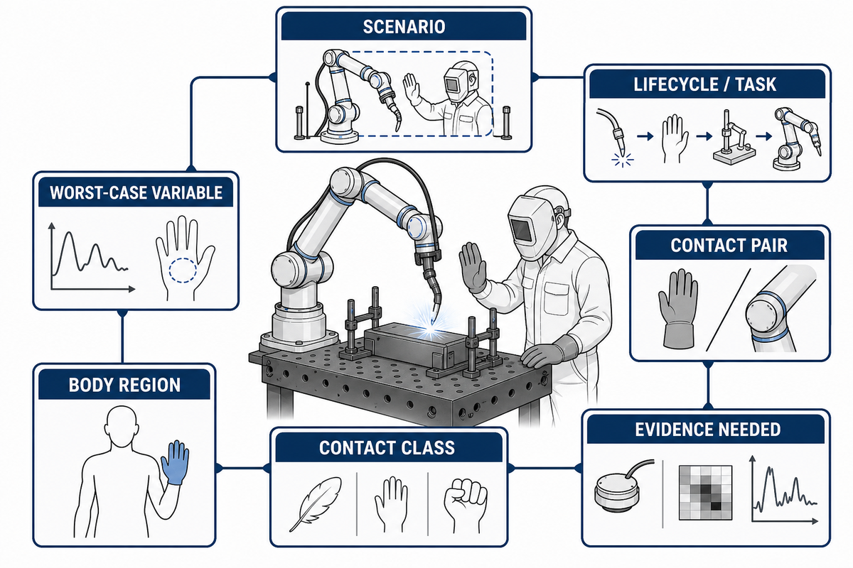
Free impacts and trapping events aren’t interchangeable. Use this matrix as a planning template, not a prefilled compliance record; replace every row with the application’s real tasks, surfaces, body regions, configurations, criteria, and measurements.
| Scenario | Lifecycle/task | Contact pair | Class | Likely body region | Worst-case variable | Evidence needed |
|---|---|---|---|---|---|---|
| CM-01 | Loading | Arm and operator | Transient | Hand/arm | Maximum reachable speed | Peak trace and geometry |
| CM-02 | Loading | Arm and fixture | Quasi-static | Hand/finger | Minimum clearance | Force, pressure, and trapping setup |
| CM-03 | Production observation | Torch body and person | Transient | Arm/torso | Tool orientation and reach | Contact fixture and raw trace |
| CM-04 | Part removal | Hot workpiece and operator | Process hazard | Hand/arm | Part temperature | Thermal control, not a PFL limit |
| CM-05 | Teaching | Arm and fixed structure | Quasi-static | Hand/arm | Manual-mode path and speed | Mode-specific safeguard record |
| CM-06 | Debugging | Cable dress and person | Transient | Upper body | Unexpected cable sweep | Foreseeable-misuse test |
| CM-07 | Tip change | Wire/electrode and hand | Sharp-contact hazard | Hand/finger | Exposed point and stored energy | Elimination or guarding record |
| CM-08 | Maintenance | Axis and fixture | Quasi-static | Hand/torso | Unexpected motion | Energy-isolation procedure |
| CM-09 | Repair | Positioner and technician | Crush/trap | Whole body | Gravity and stored energy | Isolation and blocking method |
| CM-10 | Recalibration | Moving tool and technician | Transient or quasi-static | Task-specific | Temporary setup | Revised scenario and acceptance result |
Design priority
Don’t normalize foreseeable head or neck contact merely because a table appears to contain a value. Exclude access to severe contacts through layout, clearance, sequencing, interlocks, monitored zones, or other risk controls wherever practicable.
How to Build a Defensible Validation Test
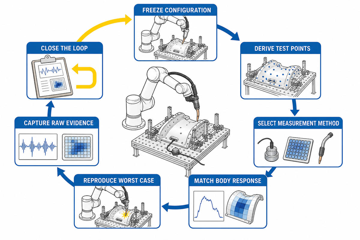
The contact map defines what a credible test must reproduce: the assessed contact, relevant body response, and worst-case application energy. Controller screenshots can’t show local pressure, trapping geometry, instrument response, or whether the tested program and payload match production.
- Freeze the bill of configuration. Record the robot, payload, torch, wire, cable dress, workpiece, fixture, positioner, program revision, safety parameters, and cell layout.
- Derive test points from the risk assessment. Convenient points on the arm don’t replace the surfaces a person can actually encounter.
- Select the measurement method. The ISO/PAS 5672:2023 catalogue describes the document’s force-and-pressure test-method scope and device-characteristic scope.
- Match the simulated body response. Document the biofidelic element, contact area, mounting, instrument identity, calibration, and validity for the selected scenario.
- Reproduce the worst case. Test reach, direction, speed, effective mass, stopping behavior, trapping clearance, and counter-surface under the frozen configuration.
- Capture raw evidence. Preserve force and pressure traces, acquisition rate, filtering, repeats, uncertainty, setup photos, and the analysis method.
- Close the loop. If a criterion fails, change the energy, geometry, surface, path, clearance, or safeguarding, then repeat the affected test and approve the final result.
Nine-record validation handover ledger
A validation result becomes reusable project evidence only when the test record connects the assessed scenario to the approved configuration. The following ledger separates the records needed to reproduce a result from the events that should reopen it.
| Checkpoint | Pass evidence | Reopen when |
|---|---|---|
| Assessed task | Named production or non-production activity | A task, access route, or user group changes |
| Contact scenario | Surface pair, body region, and trapping condition | Geometry or clearance changes |
| Robot setup | Robot, controller, firmware, and safety revision | Software, controller, or safety settings change |
| End tooling | Torch, adapter, wire, and cable-dress record | Tool mass, outline, or routing changes |
| Workholding | Workpiece, fixture, and positioner identification | A part, fixture, or positioner changes |
| Motion | Program, path, speed, reach, and direction | Programming or production rate changes |
| Instrument setup | Device identity, calibration, mounting, and filter record | Instrument or analysis method changes |
| Measured result | Raw traces, repeats, uncertainty, and pass/fail decision | A repeat is invalid or a criterion changes |
| Approval | Named reviewer, open actions, residual risks, and release date | An open action or change-control trigger is activated |
Measurement note
DGUV practice guidance discusses a fixed measuring system and at least 1 kHz acquisition for signals up to 100 Hz, with defined filtering. Treat that as attributed practice guidance, not as a fabricated quotation from ISO/TS 15066, and use the method required by the project’s licensed documents and test plan.
A Passing Contact Test Does Not Make Welding Safe
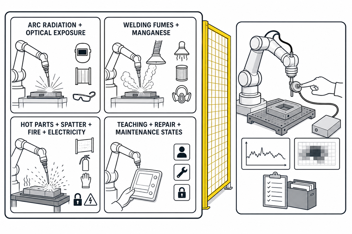
Power and force limiting addresses assessed human-robot contact. Beyond that test plan, welding introduces a second hazard layer, so the risk assessment must independently control the arc, fumes, electrical energy, heat, spatter, sharp wire and workpiece edges, fixtures, positioners, cylinders, and stored energy.
| PFL evidence can address | PFL evidence cannot establish | Separate control examples |
|---|---|---|
| Measured impact or clamping contact in an assessed scenario | Protection from arc radiation and optical exposure | Arc screens, controlled access, personal protective equipment |
| Whether applicable force and pressure criteria passed | Control of welding fumes and manganese | Process selection, local exhaust ventilation, exposure assessment |
| Tested geometry and motion configuration | Protection from hot parts, molten spatter, fire, or electricity | Thermal barriers, housekeeping, electrical safeguards, hot-work controls |
| Residual contact risks named in the dossier | Safety of untested teaching, repair, or maintenance states | Mode-specific procedures, isolation, blocking, supervision, and access controls |
OSHA’s Technical Manual on industrial robot systems separates system hazards, task states, and lifecycle responsibilities. NIOSH likewise treats welding fume and manganese exposure as a process-dependent occupational hazard, not a robot contact limit.
Welding-specific standards layer
The AWS D16 committee catalogue lists D16.1M/D16.1:2018 for robotic arc-welding safety and D16.3M/D16.3:2026 for robotic arc-welding risk assessment. Use applicable AWS documents alongside, not instead of, the robot-application risk assessment and contact validation.
Acceptance Evidence and the Change-Control Tripwire
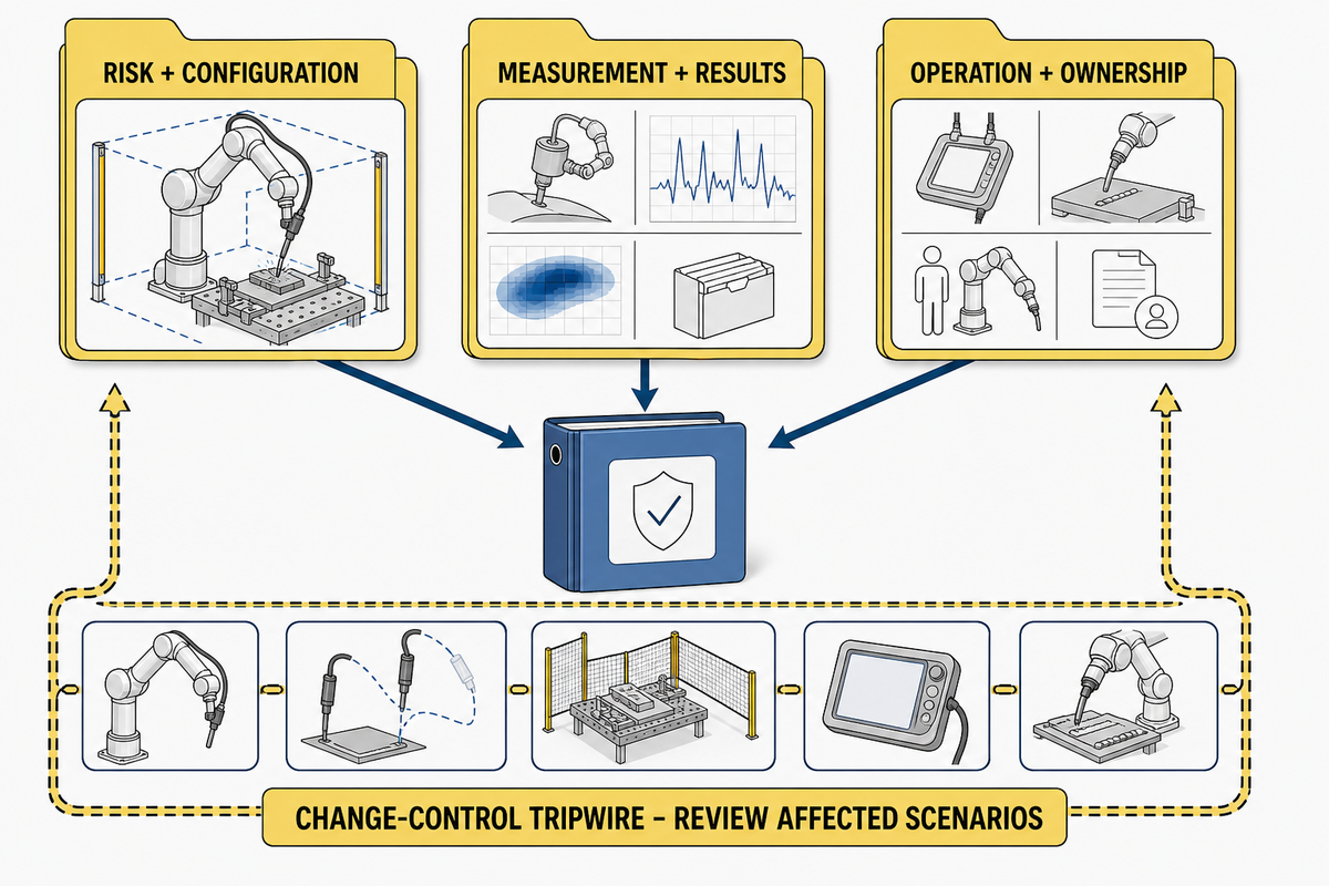
Handover should not reduce the result to “the cobot is compliant.” A useful Acceptance Dossier shows which application configuration and contact scenarios were assessed, how they were tested, what passed, what residual risks remain, and which changes reopen the assessment.
Risk and configuration
- Signed risk assessment and scenario matrix
- Robot, tool, payload, workpiece, fixture, program, and safety revisions
- Production and non-production task states
Measurement and results
- Instrument identity and calibration
- Setup photos, raw force/pressure traces, and analysis method
- Applicable limits, result, uncertainty, corrective action, and approval
Operation and ownership
- Safety-function validation and residual-risk instructions
- Named owner for site acceptance and continued maintenance
- Change-control triggers and revalidation responsibility
Who owns which evidence?
| Role | Evidence responsibility to define in the project |
|---|---|
| Robot manufacturer | Robot limitations, safety functions, integration information, and maintenance instructions. See the welding automation manufacturer profile when verifying supplier identity. |
| System integrator | Application risk assessment, safeguard design, configuration control, validation, and technical file. Define the cell boundary against the collaborative welding robot configuration. |
| Employer/user | Site conditions, procedures, training, supervision, inspection, maintenance, and management of change. Compare those duties with the supplier’s documented scope. |
| Operators and maintenance workers | Task knowledge, foreseeable misuse, access needs, observed hazards, and participation in validation. Map those tasks to the proposed collaborative welding system. |
| Acceptance authority | Signed disposition of results, deviations, residual risks, open actions, and permission to release the cell. |
What activates the Change-Control Tripwire?
- Torch, electrode, end effector, or adapter
- Payload, workpiece, fixture, or positioner
- Cable dress or hose routing
- Path, speed, reach, direction, or safety parameter
- Cell layout, access, screen, guard, or monitored zone
- Robot, controller, firmware, or safety software
- Repair affecting stopping or contact behavior
- New production, teaching, cleaning, or maintenance task
Revalidation should be scoped to the affected scenarios, and the decision must be recorded. A change that alters speed, effective mass, geometry, trapping clearance, access, or task behavior can invalidate a result even when the robot model remains unchanged.
Configuration-bound means exactly that
A passing test belongs to the tested configuration and scenario. It is not a transferable certificate for every workpiece, torch, program, speed, workstation, or operator task.
3-Gate Procurement Framework
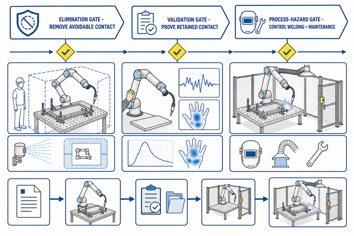
Because every passing test is configuration-bound, buyers should purchase an integration scope and acceptance record, not only a cobot arm. These three gates keep a request for quotation focused on evidence that can survive commissioning and later changes.
- Elimination gate: Can the contact, trapping point, exposed sharp feature, or hazardous access be removed by design?
- Validation gate: Can every retained contact be reproduced, measured, documented, and passed under the worst credible configuration?
- Process-hazard gate: Are welding and maintenance hazards controlled independently, and are those controls included in site acceptance?
Put these items in the request for quotation
- Required ISO, AWS, national, and customer standards with editions
- Responsibility split for the manufacturer, integrator, employer/user, workers, and acceptance authority
- Production and non-production contact-scenario inventory
- Measurement method, instrumentation, calibration, raw-data format, and uncertainty
- Welding-process safeguards, safety-function validation, and residual-risk documentation
- Acceptance dossier format, approval route, change-control triggers, and revalidation owner
When comparing a collaborative welding robot system, ask which application evidence the supplier will deliver with the cell. Product specifications are inputs to integration; they aren’t substitutes for the final risk assessment and acceptance tests.
Discuss the application before fixing the acceptance scope
Share the workpieces, fixtures, operator tasks, desired access, welding process, and planned changeover conditions. That information determines whether contact can be eliminated and what must be validated.
Frequently Asked Questions
Is ISO/TS 15066 still current after ISO 10218:2025?
View answer
Yes. As of August 13, 2026, ISO lists ISO/TS 15066:2016 as published/current and marked to be revised. ISO 10218-1:2025 and ISO 10218-2:2025 are also published. Confirm the related editions adopted by the project rather than assuming ISO/TS 15066 was withdrawn, and record that edition decision in the risk assessment and test plan.
Does an ISO 10218-1 compliant cobot make a welding cell compliant?
View answer
No. ISO 10218-1 addresses the robot, while the integrated application has its own layout, tools, workpieces, fixtures, programs, access, process hazards, and tasks. Those conditions still require risk assessment, safeguarding, validation, and documented acceptance. The torch, cable dress, hot part, sharp wire, positioner, and fixed counter-surfaces can create hazards that do not appear in a robot model’s declaration. Treat the robot documentation as one input to the cell-level decision.
Do I need to test pressure if the cobot reports force or torque?
View answer
A controller estimate does not establish local pressure. Where the selected contact criteria include a pressure limit, measure pressure with a suitable method for the body region, geometry, and contact type; also measure the applicable force rather than inferring one quantity from the other. A broad surface and a narrow edge can produce different pressure results at similar total force. Document the measuring device, biofidelic element, contact area, calibration, acquisition and filtering method, repeats, raw traces, and tested configuration. If either applicable quantity fails, change the energy, geometry, clearance, path, or safeguard and repeat the affected test.
When should a welding cobot be revalidated?
View answer
Revalidate the affected scenarios after a change that can alter contact energy, geometry, trapping, access, stopping, or task behavior. Common triggers include a different torch, payload, workpiece, fixture, cable dress, program, speed, safety parameter, layout, repair, software revision, or operator/maintenance task.
Can a welding cobot run without fencing?
View answer
Only when the application risk assessment justifies the chosen collaborative operation and all relevant hazards are controlled. A force-limited arm does not remove the need for arc screens, fume control, controlled access, interlocks, monitored zones, fixed guards, or other safeguards where the welding process and cell design require them. The justified layout may therefore use a mix of collaborative and conventional safeguards.
Specify the Evidence Before You Specify the Speed
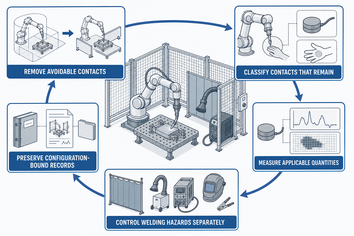
ISO/TS 15066 does not ask a buyer to accept a “safe cobot” label at face value. Project teams must make application-level decisions: remove avoidable contacts, classify those that remain, measure the applicable quantities under worst-case conditions, control welding hazards separately, and preserve a configuration-bound record.
Final acceptance question
If the torch, workpiece, fixture, path, speed, software, access, or task changes tomorrow, can your records show exactly which scenarios must be reviewed and retested? If not, the project has a force setting, not a defensible validation system.
About This Safety Guide
Wuxi Zhouxiang Complete Set of Welding Equipment Co., Ltd. designs and supplies welding automation systems, including collaborative welding solutions. This article separates robot-contact validation from welding-process controls so buyers can define a clearer acceptance scope; learn more about the team and manufacturing background on the company profile.
References & Sources
- ISO/TS 15066:2016, Collaborative robots, International Organization for Standardization
- ISO 10218-1:2025, Industrial robots, International Organization for Standardization
- ISO 10218-2:2025, Industrial robot applications and robot cells, International Organization for Standardization
- ISO/PAS 5672:2023, Test methods for measuring forces and pressures, International Organization for Standardization
- FB HM-080: Collaborative robot systems with power and force limiting, DGUV
- Soft Force and Pressure Sensors for Robot Safety Applications, National Institute of Standards and Technology
- Industrial Robot Systems and Industrial Robot System Safety, Occupational Safety and Health Administration
- Welding Fumes and Manganese, National Institute for Occupational Safety and Health
- D16 Committee on Robotic and Automatic Welding, American Welding Society