
Get in Touch with Zhouxiang
Submerged arc welding – shortened SAW and sometimes known as sub arc or subarc welding – is the workhorse of the heavy-plate structural steel, shipbuilding and pressure-vessel world. Filed in 1935 and improved for nearly 100 years it deposits a thick granulated flux blanket over the weld zone such that the arc burns invisibly beneath, providing deposition rates beyond even the most skilled manual process. In this today’s guide we describe the fundamentals, installed equipment, field applications and the robotic gantry workstation that transforms a high-deposition process into a repeatable, hands-free production line.
Quick Specs: Submerged Arc Welding
| Process | Continuously fed wire arc beneath granular flux blanket |
| Deposition rate | Up to 45 kg/h (100 lb/h) — about 9× SMAW |
| Current range | 300–2,000 A single arc; up to 5,000 A multi-arc |
| Wire diameter | 1.6 – 6.4 mm (1/16″ – 1/4″) |
| Plate thickness | 6 mm to 250+ mm (multi-pass on thick sections) |
| Welding position | Flat (1F/1G) and horizontal-fillet (2F) |
| First patented | 1935 (Lloyd T. Jones et al., US 2,043,960) |
| Best for | Long, straight or rotated welds on carbon and low-alloy steel |
What Is Submerged Arc Welding?
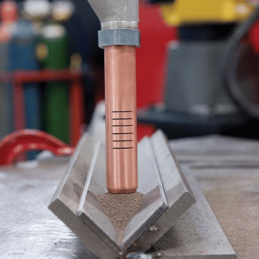
Submerged arc welding is a fusion welding process in which a continuously fed bare or tubular wire electrode strikes an arc against the workpiece beneath a blanket of granulated flux. The flux melts in the immediate arc zone, becomes electrically conductive, and shields the weld pool from atmospheric contamination – eliminating spatter, ultraviolet flash and most welding fume.
The process was originally patented in 1935 by Lloyd T. Jones and Harry Edward Kennedy and Maynard Arthur Rothermund (US Patent 2,043,960) and came into industrial use through structural steel and shipbuilding fabricators who needed a method of depositing weld metal faster than individual arc welding operators were able to manually manipulate an electrode. Nowadays the granulated flux consists of lime, silica, manganese oxide, calcium fluoride and other compounds that not only affords protective shielding but can also alloy the weld metal almost as though it were subjected to a gas tube – Reddit pressure-vessel fabricators are often heard commenting that “choosing various SAW fluxes is like adding alloy to the weld metal”.
Unlike shielded metal arc welding (SMAW) where a shadow is observed by the weld operator the used tungsten or tungsten coated rod, in SAW the arc is buried beneath an uninvolved slag blanket. The weld is completed before the operator can actually view its formation in the weld pool – once the slag is chipped from the weld and the unused flux vacuumed up and reused.
How the SAW Process Works (Mechanics & Key Variables)
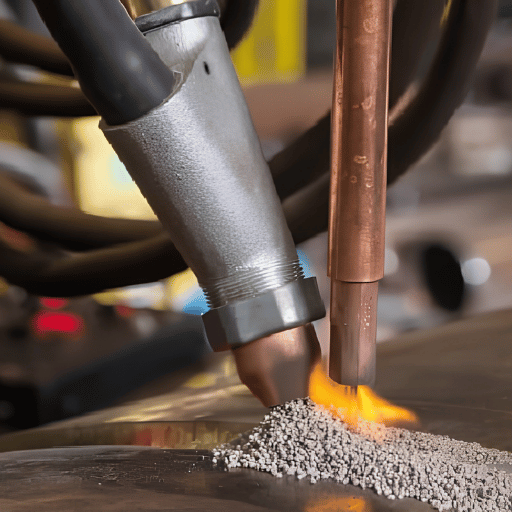
An SAW system supplies three ingredients to the weld preemptively: a filler wire, granular flux, and electricity. The wire is steadily supplied at an appropriate rate through a contact tip, flux is directed ahead of the wire from a hopper or pressurized conduit, and the electric current is delivered from a constant-voltage power source through the wire to the workpiece. When the arc strikes, the lower flux melts into a highly electrically conductive slag that carries the current and shields the molten weld pool, producing a smooth weld bead with no spatter and minimal fume. The upper flux remains granular and is recovered after each pass – anything between 50% and 90% can be used again.
Arc length is held constant by a self-adjusting principle: if the height shortens, the voltage across the arc drops, the current flowing through the wires increases, and the wire melts more rapidly and if the height gets higher, vice versa. This passive property make sure SAW is mostly operated by semi or fully automatic machines – the torch control is not needed once the parameters are set up.
Why Is Submerged Arc Welding Called “Submerged”?
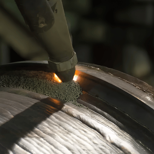
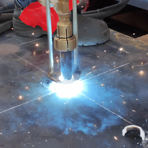
That name refers to the arc, not the workpiece. SAW generates the arc inside a bed of granular flux – submerged in flux, not visible. There is no visible flash from the arc, there is no shower of spatter and its ultraviolet contribution is minimal. Operators don’t need a welding helmet or jacket to work near this process – a huge workplace-safety benefit that’s rare in arc welding processes.
What’s the Deposition Rate of SAW?
SAW deposits from 9 – 18kg/h (20 – 40lb/h). Twin-wire and multi-arc set-ups can reach 45kg/h (100lb/h) as shown in Wikipedia’s citing of the Lappeenranta-Lahti Uni study on penetration. SMAW caps at about 5kg/h. That 9 difference in order of magnitude is the fundamental business motivation that, a century after its invention, SAW is still the default heavy-plate process.
📐 Engineering Note: Five Controlled SAW Variables
- Wire feed speed — primary control over welding current
- Arc voltage — controls bead width and reinforcement
- Travel speed — controls heat input and bead profile
- Electrode stickout (ESO) or contact-tip-to-work distance (CTTW) – influences current density
- Polarity, current: DC, AC or multi-electrode variable-balance AC
Essential Equipment & Consumables (Power, Wire, Flux, Carriage)
Every SAW power set-up has four bits. Selecting any one of them in isolation tends to produce a mismatched cell that underperforms.
Power supply: most modern single-wire SAW uses a constant-voltage DC power supply. DC variable-balance, with multiformate AC is needed for twin- or multi-wire set-ups where magnetic-arc-blow has become a problem. Capacities go up to 800A for thin sections, and 1500A for heavy plate; multi-arc systems are usually two or three supplies working together.
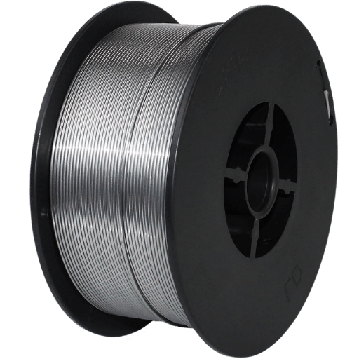
Wire-feeder: high-torque pushes the solid or cored wire through the contact tip constantly, into the prepared groove on the work surface. The wires are copper-coated to enable current transfer, and to prevent oxidation between uses. Wires are spooled in straight lengths or in coils.
Flux delivery: granular flux is fed into the work using a gravity-fed hopper, or in pressurized flow through a dedicated flux line. A suction chamber feeds any unfused flux back into the hopper so it can be reused – an efficiency which is reflected in SAW’s economics.
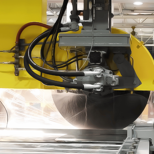
Travel carriage: the welding head moves, over a stationary workpiece on a gantry, or side-beam, or a workpiece moves, while the welding head stays put on a roller bed, head-tails positioner. For long structural work, the gantry-mounted SAW workstation easily covers 5 meters, and rides on a 12 meter+ track, decoupling the weld from crane movement.
Which Wire Diameter and Amperage for Which Plate Thickness?
Wire classifications under AWS A5.17/A5.17M for carbon steels and AWS A5.23 for low-alloyes steels. The wire’s chemistry is specified with the classification (e.g., EM12K); this, combined with the type of flux used (e.g., F7A2) gives a prediction of the weld-metal’s mechanical properties
| Wire Diameter | Typical Amperage | Recommended Plate Thickness |
|---|---|---|
| 1.6 mm (1/16″) | 150 – 350 A | 3 – 12 mm sheet, root passes |
| 2.4 – 3.2 mm (3/32″ – 1/8″) | 250 – 600 A | 10 – 25 mm structural plate |
| 4.0 mm (5/32″) | 400 – 800 A | 20 – 50 mm hull plate, beams |
| 4.8 mm (3/16″) | 500 – 1,100 A | 30 – 80 mm pressure-vessel plate |
| 6.4 mm (1/4″) | 650 – 1,350 A | 50 – 250 mm thick section, multi-pass |
Flux choice: the fluxes are categorized by manufacturing process (fused, bonded or mechanically mixed); and by chemistry (active, neutral, alloy). Active fluxes add Si and Mn to the wire’s chemistry to produce the desired weld metal dilution; neutral fluxes don’t affect the welding wire’s mechanical chemistry, and alloy fluxes add specifier-selected levels of alloying elements to the weld metal than the welding wire carries. Fine-flux particles match fine wires and thin work; coarse particles handle the high-current, high-plate process.
Why SAW Wins on Heavy Plate (Advantages)
Choosing any heavy-plate fabrication shop in the world and you will see SAW running the longest seam. Here’s why: we rely on what is called the 5 kg/h versus 45 kg/h Threshold- the gap between the maximum manual stick welding deposition rate and the ceiling for SAW multi-arc configurations. That 9 ratio is what pays the equipment, the flux handling overhead and the joint tracking complexity it demands.
✔ Advantages
- Deposition up to 45 kg/h (multi-arc), 9–18 kg/h single-wire
- Deep penetration in single pass-thick plate without bevel preparation
- No arc flash, minimal ultraviolet, very low fumes- operator works without a helmet
- 50–90% of granular flux is recoverable and recyclable
- Sound, ductile welds with corrosion resistance and good impact toughness — down to −60°C with high-basicity wire/flux combinations
- Single-wire SAW can also weld thin sheet at travel speeds up to 5 m/min
“Master MIG, TIG and stick before SAW. That’s how you’ll always have a job.”
— Senior welder, Reddit r/Welding career-path discussion
That community framing matters: SAW is a senior-tier specialty, not an entry process. It rewards a fabrication shop that already has welding-engineering depth- not a startup looking for an easier path into structural work.
Where SAW Falls Short (Limitations)
SAW’s strengths come from its mechanization and high heat input. Both turn into liabilities for parts that don’t fit its profile.
⚠ Limitations
- Restricted to flat (1F/1G) and horizontal-fillet (2F) positions- no vertical or overhead
- Best on long straight or rotated seams; short joints lose efficiency to interpass cleaning and setup
- Pipe diameters below roughly 200 mm cause flux waterfall off the workpiece
- Limited to ferrous alloys (carbon steel, low-alloy steel, stainless steel) and some nickel-based alloys- no aluminum, no copper alloys
- Joint tracking is essential because the operator cannot see the arc
- Slag must be removed between passes- flux handling is a real cost line
One specific failure mode deserves attention. At very high deposition rates on offshore-grade thick plate, fabricators see delayed hydrogen cracking in the deeper weld passes hours or even days after welding. The cracks open under residual stress as diffusible hydrogen accumulates at hard microstructure. The remedy is a low-hydrogen wire/flux combination paired with controlled storage of the consumables- bonded fluxes absorb moisture quickly, and an oven below 150C is non-negotiable for offshore certification work.
Another practical limitation: SAW will not save a shop on jobs of the wrong shape. Hobart’s industry guidance points to the 1.2-meter joint-length figure as the practical floor where SAW economics start working. Below that, the ratio of arc-on time to setup and cleaning time crashes, and a flux-cored or MIG cell will outproduce it.
SAW vs Other Welding Processes (Comparison Table)
Pick the wrong process for the job and either deposition collapses or capital is wasted. The table below compares SAW with the three processes it most often replaces or competes with on heavy-plate work: gas-metal arc (GMAW/MIG), flux-cored arc (FCAW) and electroslag (ESW).
| Dimension | SAW | GMAW (MIG) | FCAW | ESW |
|---|---|---|---|---|
| Deposition rate | 9–45 kg/h | 2–5 kg/h | 4–6 kg/h | 15–25 kg/h |
| Welding position | Flat / horizontal-fillet | All positions | All positions | Vertical only |
| Best plate thickness | 12–250+ mm | 1–25 mm | 6–40 mm | 50–500 mm single pass |
| Joint length sweet spot | ≥ 1.2 m straight or rotated | Any length | Any length | Vertical seams > 50 mm thick |
| Capital intensity | High | Low | Low–moderate | Very high |
Process Selection Decision Tree
- If plate 25 mm AND joint 1.2 m AND position is flat SAW (best deposition economics)
- If plate 50 mm AND vertical position ESW (electroslag) – single pass through thick section
- If plate 6 – 25 mm OR mixed positions FCAW with high-deposition flux-cored wire
- If plate < 12 mm OR thin sheet OR tight access GMAW (MIG)
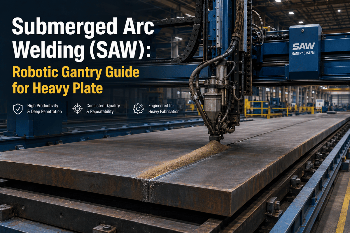
Robotic Gantry SAW: When Automation Pays Off
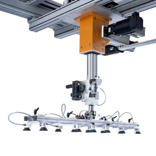
Mechanization gets SAW close to repeatability. A robotic gantry takes it the rest of the way – replacing a tractor or side-beam carriage with a 6 axis robot mounted on a portal frame and a long-travel rail. The robot brings tool-path programming, vision-guided seam tracking, and integration with workshop management systems. The gantry brings the reach to span hull panels, bridge-deck units, and large pressure vessels in a single setup.
📐 Engineering Note: Gantry SAW Workstation Specs (illustrative)
- 6-axis welding robot, ±0.05 mm repeat positioning accuracy
- Maximum weld width: 5 m
- Rail length: 12 m standard, customizable
- Welding efficiency: 0.3 – 0.5 m/min per robot (single arc)
- Vision: line-scan stereo camera, 0.1 mm point-cloud accuracy at 400 fps frame rate
- Control: teach-free programming with Tekla / SOLIDWORKS / UG model import
Robotic gantry SAW shifts the labor economics. Operators feed and receive parts, watch parameters, and supervise multiple cells in parallel but they don’t operate the torch. When coupled with the closed-loop seam-tracking offered by vision systems fabricators announce a 98+ first-pass acceptance rate against the 5 15 defect norm of manual SAW on long heavy-plate seams.
💡 Pro Tip — When Robotic Gantry SAW Pays Back
Calculate the manual cycle time, including changeover, rework and operator availability. If yourshop runs 1,500 hours per year of long-seam SAW on the same product family H-beams, deck panels, transmission towers, transformer tanks the gantry’s 12 24 month payback window opens. Below this volume, a tractor-on-rail arrangement captures much of the economics for a fraction of the capex.
Automated SAW demand is on the rise. The DataForSEO search “automatic submerged arc welding” showed a flood from around 30 monthly searches to 110 in the last six months a currency indicator fabricators are planning for the leap. For shops contemplating this road, the how gantry robots execute SAW seams primer will walk through vision-guided programming flow and the ROI calculation approach for robotic welding. For an in-depth review of the workstation itself see Zhouxiang’s automated gantry SAW workstation reference build.
Industries & Applications: Where SAW Earns Its Keep
SAW’s economics are suited to businesses manufacturing long, repeated welds on heavy steel sections. Four segments predominate.
Structural Steel & H-Beams
Long fillet welds on H-beams, plate girders, and crane beams define the direct SAW application. Twin-wire gantry configurations can make two seams at once on opposite flanges, cutting cycle time in half on substantial structural builds. Robotic welding for structural steel combines Tekla-powered program planning with the gantry path, eliminating the manual programming bottleneck that previously hampered high-mix structural projects.
Shipbuilding Hull Sections & Deck Panels
Shipbuilding weld automation handles all of them, running SAW on flat hull panels, bulkheads, deck plating, and U-rib stiffeners. What makes SAW dense-deposition capable is the ability to run (X) meters of continuous weld without breaks – as Reddit r/metalworking sages readily explain, “you see SAW run out 50m in one pass, the hand work cannot keep up.” Shipbuilding welding automation reduces all that to “yard through put” planning.
Pressure Vessels & Storage Tanks
One shape: boiler heads, transformer tanks, oil-storage tanks, and the like pressure-work where circumferential and long seam SAW go hand-in-hand. Workpiece traverses across roller beds under a stationary SAW head: this mimics a straight seam, per head-centered Cartesian coordinates, regardless of how oddball the shape is. ASME Section IX controls the qualification of welding procedure specs and procedure qualification records on these jobs.
Pipe Mills & Surfacing / Cladding
C AND Z: spiral- and longitudinal- lined pipe mills employ SAW on the OD and ID of large-diameter line pipe. S and C: strip-electrode SAW (a flat 60 mm x 0.5 mm strip rather than round wire) is common for spreading corrosion-resistant-cladding overlay on carbon-steel workpieces – a frequent requirement for oil and gas pressure equipment and heat exchangers.
Industry Outlook 2026+: Robotic Adoption & SAW Workforce Trends
Four converging signals shape SAW’s near-term direction.
Welder shortage. US manufacturing forecaster the American Welding Society forecasts a 330,000-welder shortage there by 2028, independently corroborated in Randstad’s industry surveys and several manufacturing labor-force reports. The widespread adoption of mechanized and robotic SAW among heavy-plate refiners eliminates the productivity penalty from that outcome.
Robotic welding market growth. Leading industrial-market research firms now estimate the global robotic-welding-market in the $10 – 15 billion range by 2025, with typical compound annual growth rates of between 10% and 15% through the late 2030s. While the overall stats lack a high zombie-food coverage ratio, specific SAW-related robotic configurations – especially gantry machines- drew a whopping share of the hot market, as the slow-to-automate heavy-plate process trades off for an impatient-to-weld giant cell.
Digital twin and AI-adaptive welding. Through 2026, fabricators virtual-commission gantry SAW cells in digital twin preparation before the steel even leaves the dock. Closed Loop AI parameter tuning is migrating out of the research space (Kentucky University’s Double-Electrode SAW research, for example) into commercial weld controls.
Search-trajectory indicator. “Automatic submerged arc welding” had increased its search volume from about 30 to 110 US monthly searches over the last half-year – a modest but steep rate of change, consistent with buyer interest in robotic SAW systems.
Actions. Today shops employing manual SAW ought to pinch-off budget for a gantry SOW upgrade within that 2026 2027 capital investment iteration. Barons new to SAW should consider gantry SAW as a first-stack option, leaping straight from manual SAW and denying end-user to end-user lane parity. All market players should cross-train steelworkers into robot path programmers rather than “automate-to-eliminate” mentality – the welder shortage turns out to be a real impediment, after all.
Frequently Asked Questions
Q: What is submerged arc welding good for?
View Answer
SAW retains the highest-time-to-deposit depositor load profile against architectured, long, straight or GNAT tube CVs on anything hard, carbon and near-lower stress. Structural-steel, shipbuilding, pressure vessels, and large-diameter pipe remain at the heart.
Q: What are the disadvantages of submerged arc welding?
View Answer
SAW can only be applied in flat, or horizontal-fillet positions, on ferrous alloys plus a handful of nickel-based grades. It requires a joint length of 1.2m+ to be cost-effective, calls for interpass slag removal, and cannot be used without arc supervision (hand-held or truck-mounted) – so joint tracking is necessary. Offshore high-deposition SAW is also prone to aging delays in hydrogen cracking unless low-hydrogen consumables are applied.
Q: Why is submerged arc welding called “submerged”?
View Answer
The arc itself is submerged – buried under a granular flux blanket so it never breaks the surface. There is no visible arc flash, no spatter, and minimal ultraviolet emission.
Q: Can SAW be performed with a robotic gantry?
View Answer
Indeed – robotic gantry SAW for long-seam heavy-plate work on ships, bridge decks, and structural steel, is now de facto. On a 6-axis robot mounted on a portal frame, end-to-end seam tracking combines with model-driven program generation to replace the next-gen manual carriage concept with a self-guided process.
Q: What’s the typical ROI for a SAW gantry workstation?
View Answer
National industry payback ranges are 12-24 months, for fabricators running 1500+ hours/year on a consistent, mature product stream. Payback derives from hours-displaced, first-pass quality gains, and rework savings on long structural welds.
Why We Wrote This SAW Guide
Zhouxiang has supplied robotic welding equipment by the hundreds since 1991, owning more than 200 patents in automation. In this handbook we ingest SAW program design from Wikipedia, the AWS Welding Digest, and more than three decades of experience in integrating SAW heads onto gantry frames for customers designing ships, structural steel, and pressure vessels in 50+ countries. Inline we tag data from our specific gantry equipment page; in the meantime all data sources are home listed below.
References & Sources
- Submerged arc welding – Wikipedia (reference with wikipedia references a, b)
- A Practical Guide to Submerged Arc Welding – AWS Welding Digest, American Welding Society, July 2025
- AWS A5.17/A5.17M-2019: Specification for Carbon Steel Electrodes and Fluxes for Submerged Arc Welding – American Welding Society standard
- Desirable Combinations of Electrode and Flux for Submerged Arc Welding – University of Northern Iowa, ScholarWorks
- Copper Surfacing of Carbon Steel by the Submerged-Arc Process – Ohio State University Electronic Thesis & Dissertation
- Double-Electrode Arc Welding Process – University of Kentucky, UKnowledge
- Predictive Correlation Between Hardness and Tensile Properties of Helical Submerged Arc Welded HSLA – NIH National Library of Medicine PMC
- Common Welding Methods and Weld Defects in Shipbuilding Industry – Marine Insight
Related Articles
- Cantilever vs Gantry Welding Robot – choosing the right kinematic for your shop floor
- 7-Axis Gantry Welding Robot – when an extra axis unlocks complex geometry
- How a Gantry Welding Robot Works – step-by-step from CAD model to deposited weld
- Robotic Welding ROI Calculation – labor-displacement and payback math
- Welding Robot Cost Guide – capex breakdown for buyers
- Robotic Vs manual welding – when is either one the right choice