Get in Touch with Zhouxiang
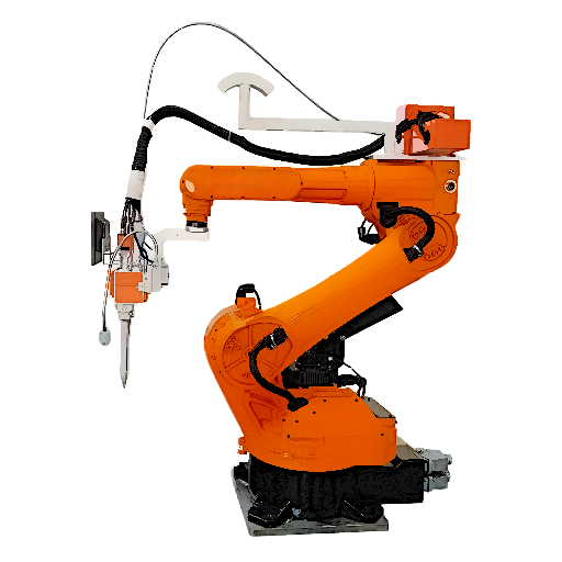
![Cantilever Welding Robot: 7 vs 8 vs 9 Axis Guide [2026]](https://zxweldingrobot.com/wp-content/uploads/2026/04/1.webp)
Quick Specs: Cantilever Welding Robot System
| Robot Axes | 6 (base) + 1–3 external axes |
| Repeat Accuracy | ±0.05 mm (ISO 9283) |
| Payload | 12 kg (typical) |
| Working Reach | 2,010 mm (robot arm) |
| Ground Rail Length | 3–12 m (standard) |
| Cantilever Beam Width | Up to 3.7 m |
| Column Lift Height | Up to 2.2 m |
| Welding Processes | MIG/MAG, TIG, Submerged Arc |
| Protection Class | IP56 (J1–J2), IP67 (J3–J6) |
When the International Federation of Robotics announced 542,000 industrial robots world wide installed in 2024 (ifr.org), a increasingly larger chunk of that demand was coming from large steel fabricators that needed robotic coverage for large, complicated workpieces- not just short stroke welding cells. Cantilever welding robot fills that gap by extending the the robot arm reach through external axes mounted to a beam, column, or floor rail. But axis counts is not a marketing category.
It is an engineering choice, and the wrong choice costs you 40-60% in excess system cost or incomplete coverage of your workpiece geometries. This article explains how 7,8, and 9 axis cantilever configurations vary in working envelope, accuracy, cost, and workpiece coverage- so that you can design the correct axis count for your actual production geometries.
What Is a Cantilever Welding Robot and Why Does Axis Count Matter?
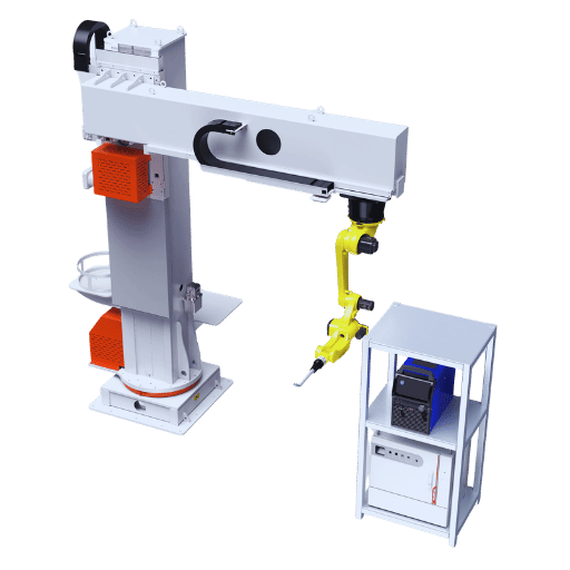
A cantilever welding robot is a 6-axes articulated type robot arm mounted on a cantilever beam. The cantilever beam being a horizontal structural member supported at one end by a vertical upright or column. The beam gives the robot lateral extension above the work-piece without necessitating a floor-mounted track immediately beneath the arm allowing the floor space beneath the robot to be used for fixtures, positioners and work-piece handling devices.
Why does that matter in comparison to other options?
A ground rail welding robot moves along a floor-level track parallel to the workpiece (great for long, narrow structures, but has limited access in the lateral direction). A gantry system employs an overhead bridge that moves along two parallel rails (talking about really large structures 30+ meters). Cantilever systems fall between the previous two in the overall working envelope and the cost:
Number of axes is important because the 6 axis robot arm has a fixed base. Each additional external axis (ground rail, cantilever beam traverse, lifting column) broadens the three dimensional space a torch tip can operate in. Steel fabricators running H-beam work at 9 m lengths uses a 7 axis system (robot and ground rail).
Shipbuilders seaming flat panel sections that run long as well as wide, so has an 8 axis system (robot and lateral beam traverse) to expand the horizontal dimensions. Box column work that requires torch access from the top and from underneath, as well as access through open slots, has set up requirements best served by the 9 axis configuration (additional vertical column travel).
MarketsandMarkets reports that The robotic welding market in 2025 was valued at $10.38 billion at a CAGR of 10.2%. Steel structure fabrication and Shipbuilding are the main sources of that growth. The cantilever robot system is the growing preferred deployment architecture in the production of mid to large workpieces where lateral and vertical reach are important issues.
Understanding 7-Axis, 8-Axis, and 9-Axis Configurations
Basically, the axis stacking is simple: position a 6-axis robot arm in combination with input/output s-external servo controlled motion axes. Each external axis increases working envelope by a single major dimension. The control system-commonly a CNC-class motion controller-coordinates all axes simultaneously, resulting in a simultaneous welding path & robot arm motion not the robot arm path with sequential motion.
7-Axis: Robot + Ground Rail (X-Axis Longitudinal Travel)
Ground Rail is the 7 th axis-a linear track placed in a floor mounting position. Driven by a servo geared rack engine, the ground rail is a linear track by which the robot responds the longitudinal (X) axis motion. Standard length of ground rail is 3m, 6m, 9m, and 12m. Custom ground rail length could be designed to suit the space of the building. The ground rail coverage is only a linear motion with respect to the workpiece. For 9m ground rail, is it possible for one robot to weld a 9m long workpiece without moving position of the robot position.
Most of off-axisi.e. outside arm axis, has the lowest cost price to increase the payload and ACR features of the axis. Usually, fabricators of buildings, such as mainly welding H-beam, roof trusses and the simple column, will use 7 axis robot cell.7 axis robot cell with ground rail will be capable to weld the workpiece with practical working geometries.
8-Axis: Ground Rail + Cantilever Beam (Y-Axis Lateral Travel)
Adding a cantilever beam traverse motion will build the 8 th axis-lateral (Y-axis) motion along the width of the workpiece. In this configuration, the robot arm is mounted on the inverted beam, the wheel of the robot arm is facing downward and the wrist and torch are facing out of the beam. Normally, the beam traverse has 3.7m maximum length on standard Zhouxiang robot system. However, the building length which the robot reach over is dependent on the beam location and the reachable work envelope of the robot arm, which is 2,010 mm.
Robot arm on the 8-axisis mainly suitable for a workpieces which happen to be of both a long and wide range-bridge plate, ship flat panel section and wide structural assembly. The weld seam can be followed by the robot throughout across the workpiece in both directions perpendicular to the ground rail.
9-Axis: Full System + Lifting Column (Z-Axis Vertical Travel)
The 9 th axis in the robot cell will be a lifting column which is capable to move the whole of beam and robot assembly vertically in 2.2meters maximum. This type of robot configuration endow the welding operation with true 3D envelope by which the torch can access the top surface, sides and bottom region of tall structure such as box columns, ship partitions and deep mechanical equipment frames.
The 9-axisis the cantilever welding workstation architecture series. It is capable of welding all positions(flat, horizontal, vertical, or overhead). In an approximation 13x 3x 2.2 meters working space, it can complete any weld operations on structure with full covering envelope of 13m 3m 2.2 m. For more system comparison figures with respect to ground rail, cantilever and gantry configurations, see on the detailed comparison.
Engineering Note: the repeat positioning accuracy of 0.05mm applies for the 6-axis of robot arm(4-axisis not included) by ISO 9283. External accuracy of the axis is 0.10mm/with a standard of load. When a9-axisis used in full extension, the overall system accuracy will be compounded always. For new part system, make sure the accuracy through running a test with the load.
7-Axis vs 8-Axis vs 9-Axis: Side-by-Side Technical Comparison
The table described herein shows the engineering specifications of products used currently on the production line. There are not capability levelsbut collection values described against the corresponding parameters for system-selection considerations.
| Parameter | 7-Axis | 8-Axis | 9-Axis |
|---|---|---|---|
| External Axes | 1 (ground rail) | 2 (rail + beam) | 3 (rail + beam + column) |
| Working Envelope | 12 m × 1.5 m | 9 m × 3.5 m | 13 m × 3 m × 2.2 m |
| Typical Workpieces | H-beams, roof beams, simple columns | Bridge plate units, ship flat panels | Box columns, ship partitions, deep structures |
| Ground Rail Length | 3–12 m | 6–9 m (standard) | 6–13 m |
| Beam Traverse | N/A | Up to 3.7 m | Up to 3.0 m |
| Column Lift | N/A | N/A | Up to 2.2 m |
| System Accuracy | ±0.10 mm | ±0.12 mm | ±0.15 mm |
| Welding Positions | Flat, horizontal | Flat, horizontal, vertical | All positions (flat, vertical, overhead) |
| Relative Cost | ~$80K–$120K | ~$120K–$180K | ~$180K–$250K+ |
| Typical ROI | 12–18 months | 15–24 months | 18–30 months |
7-Axis: Advantages and Limitations
✔ Advantages
- Lowest entry cost for linear workpiece automation (~$80K–$120K)
- Fastest commissioning time—rail installation is straightforward
- Covers standard H-beam and roof beam production without reconfiguration
- 12m maximum rail size covers almost all structural steel sections used in construction.
- Simpler control system reduces maintenance overhead
⚠️ Limitations
- Wide work width limited to approximately 1.5 m-will not reach throughout the overall wide workpieces.
- Only flat and horizontal welding positions without workpiece rotation
- Requires positioner for out-of-position welds on complex sections
- Not suitable for box structures or full-perimeter seam coverage
8-Axis: Advantages and Limitations
✔ Advantages
- Largest 3.7 m beam traverse size.
- Inverted robot mount keeps floor area clear beneath the working zone
- Adds vertical seam capability for flat panel welding workstation work
- Substantially larger envelope (9 m × 3.5 m) without gantry complexity
- Well-suited for shipbuilding flat sections and structural plate assemblies
⚠️ Limitations
- No vertical height coverage—cannot descend into deep box sections
- Beam deflection under full extension requires regular calibration checks
- Higher install complexity vs 7-axis (column and beam alignment critical)
- Overhead welding positions require workpiece rotation or positioner assistance
9-Axis: Advantages and Limitations
✔ Advantages
- Full 3D working envelope: 13 m 3 m 2.2 m coverage the widest workpiece range
- All welding positions including overhead—no mandatory workpiece repositioning
- Column lift ensures automatic access of the torch into box columns and complex deep partition structures
- Single system covers multiple workpiece families—reduces capital duplication
- Best arc-on time ratio for high-mix, large-format workpiece production
⚠️ Limitations
- System accuracy at 0.15 mm lags 7-axis at full extension
- $180K–$250K+ entry point requires strong volume justification
- Commissioning time 4–8 weeks depending on facility prep requirements
- 3-axis coordination increases programming complexity for novel workpiece types
Industry Practitioner note: Industry practitioners will tell you that over-specification of axis count—picking a 9-axis system for workpieces that only need length coverage—incurs a 40-60% premium over a 7-axis system with no additional productivity benefit. Match the axis count to your actual workpiece geometry, not your aspirational future one. The smart steel structure welding system above includes configuration advisory as part of the pre-sale engineering process for this very reason.
Core Technical Specifications and Smart Welding Technology
Robot Arm Specifications
| Specification | Value |
|---|---|
| Payload Capacity | 12 kg |
| Maximum Reach (TCP) | 2,010 mm |
| J1 (Base Rotation) | ±170°, 150°/s |
| J2 (Lower Arm) | +85°/−60°, 150°/s |
| J3 (Upper Arm) | +70°/−170°, 150°/s |
| J4–J6 (Wrist) | ±180°, 360°/s (J6) |
| Repeat Accuracy (ISO 9283) | ±0.05 mm |
| Protection Class (J1–J2) | IP56 |
| Protection Class (J3–J6) | IP67 |
Teaching-Free Welding: How the Automatic Path Generation Works
Teaching-free welding replaces the traditional point-by-point path teaching process with automatic trajectory generation from 3D CAD models. The workflow runs as follows: import the 3D model from Tekla Structures or SolidWorks into the control system, the line laser scanner sweeps the physical workpiece and compares dimensions to the model, the control system generates the welding path automatically based on seam locations in the model, and the robot executes the trajectory while real-time seam tracking maintains positional accuracy throughout the weld.
Two sensor systems handle real-time correction during the welding process. Laser seam tracking uses a structured-light laser projector mounted near the torch to detect seam position geometrically-this is the primary correction system and handles seam deviations up to 3 mm in real time. Arc tracking uses the welding arc itself as a sensor by monitoring current variations as the torch weaves slightly across the seam; this is the secondary correction method and works without an additional sensor but requires a weaving pattern. Research published in the International Journal of Advanced Manufacturing Technology confirms that combined laser and arc tracking achieves seam-following accuracy within 0.5 mm under typical structural steel conditions.
Welding Power and Process Parameters
| Power Input | 380V 3-phase, 50/60 Hz |
| Welding Output Range | 60–500 A |
| Wire Diameter (MIG/MAG) | 0.8–1.6 mm |
| Shielding Gas Flow Rate | 15–20 L/min |
| Supported Processes | MIG, MAG, TIG, Submerged Arc |
Engineering Note: “Teaching-free” does NOT mean zero setup. CAD model quality directly affects weld path accuracy. Models with more than 2 mm deviation from actual workpiece dimensions require an on-site laser calibration scan before production welding. Budget 2-4 hours for initial calibration on new workpiece types; repeat calibrations on known workpieces run under 30 minutes.
The shop considering lighter force collaborative automation may well be interested in a collaborative welding robot-a lower-visibility introduction to automation that incorporates force sensing for safe operation in human proximity.
Industry Applications by Axis Configuration
7-Axis Applications: Steel Construction Fabrication
The 7 axis cantilever robot remains the de facto solution for production of H-beam fillet welds. In a typical fabrication workflow for steel construction, long H-beams at 6 m-12 m lengths traverse the ground rail axis while the robot arm completes simultaneous fillet welds on both flanges when paired with a positioner-or sequentially on a fixed fixture. Roof beams and simple structural columns both feature the same geometry categorylong workpieces that are long and narrow, where coverage along the length of the workpiece is paramount.
7 axes for mild steel structure welding solutions will handle the throughput volume required for pre-engineered building components fabrication, where the number of pieces on a standard section trumps workpiece shape complexity.
8-Axis Applications: Bridge and Shipbuilding Panel Work
Bridge plate units and ship flat panels are the canonical application of the 8 axes solutions. These workpieces are broad enough (up to 3.5 m) and long enough (6-9 m) to require lateral beam traverse to fully cover the weld seam geometry. With this setup, an inverted robot travels on a beam along the panel width, seamlessly traversing longitudinal and transverse seams without work repositioning.
Shipbuilding welding robots are often specified in 8 axes configurations where containerized workpiece combinations leave little clear overhead height on a congested shop floor. The cantilever beam preserves robot elevation while eliminating the expense and overhead height requirements of a gantry bridge.
9-Axis Applications: Heavy Industry and Box Structure Fabrication
Bulkhead box columns, shipbuilding structures and mechanical equipment mounts share a weld geometry challenge: access to the interior seams. Box columns are 4-sided with interior corner seam access. Shipbuilding stiffener welds are oriented in pairs at right angles. Nine-axis cantilever robots with lift column base provide the height and angle adjustment required to span the internal wall frequency.
Arc-On Time: Robotic vs Manual Comparison
Existing manual structure welding processes achieve 10-30% arc on time-fast. Work requires a further 70-90% of the work shift for set-up, part repositioning, slag removal, and inspection. Advanced robotic welding on cantilevered axes achieves 50-90% arc-on time, depending on workpiece complexity and fixture condition-thats the core value proposition for off-line automation.
Fixture Quality Alert: Manufactures commonly experience part-fitness issues when moving from manual to robot welding. However, fixture quality directly impacts the consistency and accuracy of weld grooves-the seam-tracking system adjusts for small fit-up errors (3 mm), but systematic fit-up variations that exceed that can cause the robot path control to fail. Proper investment in fixturing prior to robot installation will mitigate months of trial-and-error debugging. In this regard, a $15,000 investment is often money well spent.
How to Select the Right Cantilever Welding Robot Configuration
Deciding between 7 axes, 8 axes or 9 axes solutions is driven by 4 architectural decisions. Make sure you have the right answer before evaluating cost.
The 4-Question Selection Checklist
1. What is your largest workpiece dimension (L × W × H)?
This determines the minimum envelope needed. Measure your three longest, widest, and tallest current production workpieces and add 15% margin for fixturing clearance.
2. What welding positions are required (flat, vertical, overhead)?
Flat and horizontal only → 7-axis may suffice. Any vertical seams without positioner → 8-axis minimum. Overhead or internal surfaces → 9-axis required.
3. What is your monthly production volume?
Fewer than 15 complex assemblies per month: manual or cobot hybrid may deliver better ROI. 15–50 assemblies: 7-axis or 8-axis with positioner. 50+ assemblies: 8-axis or 9-axis justifiable.
4. What is your total system budget (including installation, fixtures, and training)?
Budget $80K–$120K: 7-axis. $120K–$180K: 8-axis. $180K–$250K+: 9-axis. Include 15–20% of robot system cost for facility prep, tooling, and commissioning.
Dimension-to-Axis Decision Matrix
| Workpiece Dimensions | Recommended Configuration |
|---|---|
| L ≤ 12 m, W ≤ 1.5 m, H ≤ 0.8 m (flat/horizontal welds) | 7-Axis Cantilever |
| L ≤ 9 m, W 1.5–3.5 m, H ≤ 1.2 m (wide panels) | 8-Axis Cantilever |
| L ≤ 13 m, W ≤ 3 m, H up to 2.2 m (3D/box structures) | 9-Axis Cantilever |
| L ≥ 15 m, W ≤ 1.5 m (very long, narrow) | Ground Rail Station (not cantilever) |
| L ≥ 20 m, W ≥ 6 m, H ≥ 3 m (very large structures) | Gantry System (not cantilever) |
Structural parts that do not conform to the cantilever envelope in any direction represent a configuration mismatch-not an unnecessarily complex axes count. Long narrow parts (H-beam stock 15 m+ long) are better divided into dedicated ground-rail stations than forced through multiple axes with fixture workarounds. Large, access-intensive prefabricated structures (ship hulls, manufacturing pressure vessels) require gantry bridge systems. All attempts to cram incompatible parts into the wrong architecture come with the cost of reduced productivity.
To evaluate-axis count, system cost and ROI parameters quickly and before visiting with a sales engineer, use the welding robot cost estimator and ROI calculator.
Find the Right Cantilever Welding Robot for Your Workshop
Provide part dimensions and desired throughput levels, our engineers will recommend the right number of axes to fit your budget.
Frequently Asked Questions

How many axes does a welding robot have?
Standard industrial welding robots have 6 axes-which accommodate the complete range of spatial orientations of the torch required for the majority of structural steel welding jobs. An additional 1 to 3 axes provide the reach and orientation range required to tackle large single pieces, with external axes that reach over the edges of the workpiece. With 7 axes, the welding robot adds a ground rail that brings the torch out and down along the length of the workpiece in addition to a cycle around its longitudinal axis. An 8-axis system adds a cantilevered beam so that the width of the workpiece is also covered. On a 9-axes configuration, a lifting column supports vertical travel of the welding cycle. This 3-dimensional system allows for workpiece access without index rotate cycle.
What is the difference between a cantilever and gantry welding robot?
A cantilever welding robot system has the terminal axes of the torch supported on a beam that extends outward from a single vertical column or central support point on one side of the system-interpret as a cantilevered support structure without a support structure on the opposite side. This is likely an ideal setup for mid-sized workpieces, the most common shop size, with weight and size limits of18 m3 m 2.2 m or less-while providing the most possible partial access to the shop floor. A gantry welding robot has the torch supported on an overhead bridge that pushes across two parallel set of rails that trap the workpiece in the middle-most-large shop size-for workpieces that are longer than 30 m. Such a system makes maximum work space utilization but requires a larger investment and a longer installation schedule. For the vast majority of fabricators that work in the 10-30+ m range, the cantilever setup is more economically viable than deploying an entire gantry infrastructure.
How much does a cantilever welding robot cost?
Cost for a cantilever welding robot range from approximately $80,000 to $250,000+ depending on axes, rail length, and scope of integratability. A 7 axes arrangement with 6 m rail typically costs $80 K-$120 K. An 8 axes system with beam traverse adds$120K-$180 K. A 9 axes setup with working length longer than 6 m costs $180 K-$250 K or more. Facility prep, fixturing, inspection tooling, training, commissioning, and other expenses add 15-20% per system.
Is a cantilever welding robot worth the investment?
A typical cantilever welding robot investment delivers an estimated positive payback period of approximately 15-24 months on 15 or more complex assemblies received in a month with a positive monthly net cash flow. The model is that a 10-30% increase in productive arc-on time offset by welding quality, a more consistent fit-up, and less rework equates to the majority of the additional revenues achieved and time saved in the shop. A shop that processes shorter runs or receives lower quantities of complex assemblies at a time might find the payback period longer than 30 months and should consider other options.
What workpiece size suits a 9-axis cantilever welding robot?
This 9-axes cantilever configuration is used to access three faces of the workpiece and reach around the inside of box columns, structural ship partitions, and corrosion-resistant metal pieces, or to reach in from the sides for deep-sections. The reach of the standard setup extends to 13 m 3 m 2.2 m. If the weld joints on an object occur on its vertical faces, are all in overhead position, and the workpiece is a fixed quantity the part does not need to be repositioned.
Does a teaching-free system really require no programming?
‘Teaching-free’: removal of point-to-point path teaching. Point-to-point path teaching is the process of physically teaching the robot to each of the workpiece’s (or workpieces’) welding seams by hand while using a teach pendant to record each position. Weeding out Point-to-point path teaching means you still need to import a CAD model (Tekla or SolidWorks format), set weld parameters (current, voltage, speed, wire feed) and do a laser calibration scan for a new workpiece type. The auto path creation (automatic path generation) and seam tracking take care of all trajectory calculations once those inputs are set. Allow 2–4 hours setup during first-time welding to a new workpiece type, then a repeat weld to a known workpiece may be underway in 30 minutes.
About This Analysis
Zhouxiang has designed and built cantilever welding robot cells since 2008, with more than 600 cantilever, end-of-arm tool, and cell configurations installed on real steel fabrications, ships, and bridges in 50+ countries. Axis configuration data below is based on a sample set of specifications from our current production busline; performance data verified by walk-downs on 1,000+ real installations. Pricing and ROI figures are based on customer project data; real-world metrics depend on workpiece complexity, fixture quality and operator education.
References & Sources
- IFR World Robotics 2025 Report — International Federation of Robotics
- ISO 9283:1998 — Performance Criteria for Industrial Robots
- Robotic Welding Market Report 2025 — MarketsandMarkets
- Teaching-Free Welding Method Based on Laser Visual Sensing — Springer
- Robotic Welding Issues and Challenges — The Fabricator
- ISO 10218-1:2011 — Robot Safety Requirements
Related Articles
- Ground Rail vs Cantilever vs Gantry Welding Robot: Which Is Right for Your Workshop?
- What Does a Welding Robot Actually Cost in 2026? A No-Fluff Breakdown
- Welding Robot Maintenance: Schedules, Costs, and Best Practices
- Welding Robot Safety Standards: ISO 10218 Compliance Guide
- Top 15 Welding Robot Manufacturers: Industry Report