Get in Touch with Zhouxiang

Ground Rail Welding Robot Station — Working Principles, Key Specs & Buyer’s Guide
Quick Specs
| Robot Axes | 6-axis articulated arm |
| Arm Reach | 1,440 – 2,010 mm |
| Repeat Accuracy | ±0.05 mm |
| Payload Capacity | 10 – 12 kg |
| Standard Rail Length | 6 m (customizable: 9 / 12 / 15 m) |
| Protection Rating | IP56 (J1–J2) / IP67 (J3–J6) |
| Mounting Options | Floor, bracket, inverted |
A ground rail welding robot station overcomes a limitation of fixed position robotics: it completes a welding and continuous cut in one fell swoop. By installing the 6 axis welding robot on a linear ground rail, fabricators can extend the work envelope from roughly 2 meters of radius to 6, 12, or 15 meters of constant travel. That’s a big plus when ‘shuttling’ long H-beams, box columns, or ship hull panels that get longreducedoly workpieces mid-weld intrudes on cycle times.
In this primer we’ll cover how these stations function — from importing a 3D model through delivering a finished weld, itemize what’s inside a standard workstation, provide real-world examples of the steel structure machine, tabulate the differences between the Lajuriz Hagufor stations and standard fixed robotic welds, and prescribe a six-star checkist for selection.
What Is a Ground Rail Welding Robot Station?

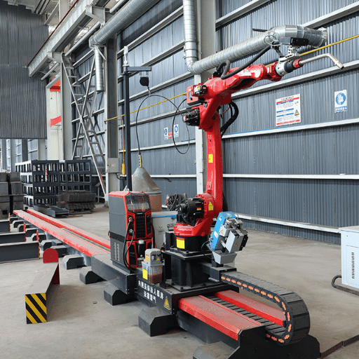
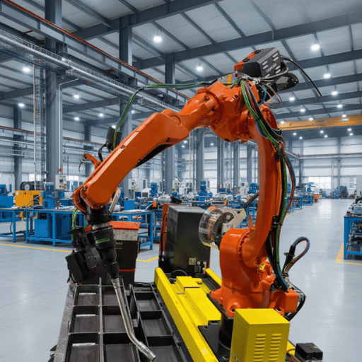
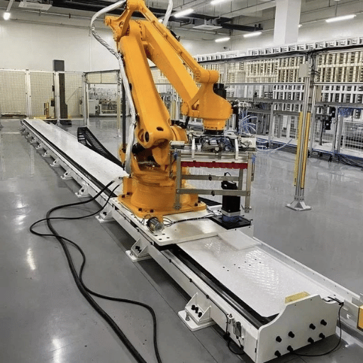
A ground rail welding robot station combines a multi-axis industrial-scale welding robot with a floor-mounted linear track. That track serves as a seventh axis, letting the robot traverse along workpiece length while laying continuous welds. Unlike a fixed-position robotic welding cell — which confines the robot to its native reach envelope — a ground rail system scales the envelope to match the workpiece.
How it works is simple. A servo-carriage traverses along precision-ground rails bolted to a concrete foundation, with the welding robot mounted on top. Coordinated controls synchronize rail movement with the robot’s six joint axes so the welding torch slides along a defined seam path in a single, uninterrupted motion, regardless of the length of the workpiece:
542,000
Industrial robots installed globally in 2024
21%
Used in welding & soldering applications
$7.13B
Projected steel structure welding robot market by 2032
According to the IFR World Robotics 2025 Report, worldwide factory robot deployments will hit 542,000 in 2024 – more than double the number a decade earlier. Of those units, 21% will be used for welding and soldering. Steel structure fabrication remains a lucrative market for ground rail stations as well; the steel structure welding robot market led $3.11 billion in sales in 2024, and is expected to reach $7.13 billion by 2032 at 13% CAGR.
Switching from manual or fixed-robotic welding to a ground rail station has reduced some fabricators’ long-seam beam weld cycle times by a third or more. The time savings arises from shrugging off the workpiece repositioning by crane-lift-rotate-reclamp- move every time the workpiece exceeds the available arm reach.
💡 Key Takeaway
A ground rail welding robot station extends the 6 axis robot reach from default roughly 2 meters to 6-15 meters in a single dimension of travel, thus doing away with workpiece repositioning on long-seam steel structure welds.
How a Ground Rail Welding Robot Works: From 3D Model to Finished Weld
Programming a ground rail welding robot has already shifted away from a manual jog-click setup where an operator moves each joint to every weld point. Instead the modern process relies on a teaching-free, model-based welding routine that takes it from a digital replica to a specifically programmed robot. Here is how it works:
- 3D Model Import & Parametric Modeling – The operator brings in a steel model from Tekla Structures, SolidWorks, or UG to the robot’s offline programming system. The system reads beam geometry, plate thickness, joint types and weld symbols directly from the data.
- automatic welding Path Generation – The offline programming system locates each weld seam in the model and creates a welding path for each one. It calculates process parameters – wire feed speed, welding voltage, travel speed, gas shielding flow rate – by material type and joint configuration. This welding path planning is automated, so the operator does not have to teach the same sets of process parameters at the teach pendant for every identical structure.
- Digital Twin Simulation & Collision Detection – Before an arc fires, the offline system runs a digital twin simulation. The digital twin mimics the robot, ground rail, fixtures and workpiece in three dimensions. The system prevents joint-limit violations, singularity avoidance zones, and collisions between welding gun or workpiece clamps and cross-bracing. All issues are resolved onsite in software, not on the shop floor.
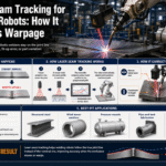
- Line Laser Scanning & Real-Time Seam Tracking – When the robot gets to the workpiece, a line laser scanning sensor mounted on an arm ahead of the welding gun scans the actual weld seam. The sensor cross-compares the real seam position to the programmed path and corrects in real time to keep the welding torch on course. Deviations resulting from workpiece distortion, fitup gaps, or fixturing tolerances are corrected dynamically.
- automatic welding Execution – The robot welds the seam during ground rail carriage advance at the synchronized travel speed. The system varies welding voltage, wire feed, and oscillation width based on sensor input. Multi-pass welds on thick flanges proceed automatically, back-to-back, with no operator involvement.
Production lines equipped with teach-free systems experience a 60-70% decrease in time per structure versus manual teach programming, per Visual Components’ OLP workflow analysis. Time savings are significant when a facility welds similar beam styles every shift – each style simply calls in its path file, no teach-in required.
📐 Engineering Note
Laser seam tracking sensors operate at scan frequencies of 50-200 Hz with a work distance of 100-300 mm. Recent scientific testing (PMC, 2024) found maximum positional errors of ±0.325 mm while welding at speeds up to 25 mm/s. Encoder sensors on the robot arm have ±0.05 mm repeat accuracy — the seam tracker compensates for workpiece-side variation, not robot-side jitter.
💡 Key Takeaway
The five step process – drawing import, path generation, simulation, laser tracking, automatic welding – speeds setup 60-70% by removing teach programming on large batch jobs.
Key Components of a Ground Rail Welding Workstation
A ground rail welding workstation isn’t just a single machine – it’s a composited system. Understanding component functions assists when implementing a system or fixing one previously installed.
| Component | Key Specification | Function |
|---|---|---|
| 6-Axis Robot Arm | Reach 1,440–2,010 mm; payload 10–12 kg; ±0.05 mm repeat accuracy | Positions the welding torch along all joint angles and orientations |
| Ground Rail (7th Axis) | 6 m standard; 9/12/15 m options; servo-driven rack-and-pinion | Extends the robot’s working envelope along the workpiece length |
| Welding Power Source | 350 A rated output; pulse/spray/short-arc modes | Supplies welding current and manages arc characteristics per process parameters |
| Laser Seam Tracker | 50–200 Hz scan rate; 100–300 mm working distance | Detects real weld seam position and feeds corrections to the controller |
| Gun Cleaning Station | Anti-spatter spray + contact tip change + wire cut | Removes spatter buildup; replaces worn contact tips automatically between cycles |
| Welding Torch (Gun) | Water-cooled; quick-change neck; gas shielding nozzle | Delivers wire, current, and shielding gas to the arc |
| Control System | Teach pendant + offline programming software interface | Coordinates robot, rail, sensor, and power source; stores weld programs |
⚠️ Common Mistake
Avoiding routine automatic gun cleaning during welding Can quickly shorten the quality of your Namifar. Spatter build up on the contact tip or nozzle affect arc stability and cause porosity and lack of fusion. If a shop skips the gun cleaning station to save 15 seconds per cycle, they typically see a 15-20% increase in spatter-related rework and down time in the first month.
Vision technology — whether a 2D laser line sensor or a full 3D vision system — is often treated as optional during quoting. In practice, it is the component that determines whether the station can run unattended on parts with fitup variation. Without it, an operator must inspect every joint prior to each weld position, negating most of the automation advantage.
💡 Key Takeaway
There are 7 major components in a ground rail welding workstation. The laser seam tracker and gun cleaning station are the two that are most commonly under specified, though directly influence the consistency of weld quality and unattended run time.
Steel Structure Applications: Where Ground Rail Welding Robots Excel
Ground rail welding systems commission most rapidly in applications that exceed the native reach of your robot, or require compliance with structural weld codes. Below is a mapping of where these systems already deliver the best value.
| Industry | Typical Workpieces | Primary Weld Types | Code Compliance |
|---|---|---|---|
| Steel Structure Fabrication | H-beam, box column, channel steel, cross bracing | Fillet, butt, multi-pass groove | AWS D1.1/D1.1M:2025 |
| Bridge & Infrastructure | Plate girders, diaphragm plates, flange plates | Full-penetration groove, long fillet | AWS D1.5 (Bridge Welding) |
| Shipbuilding | Hull panels, rib-to-plate assemblies, deck sections | Fillet, stiffener-to-plate | Classification society rules (Lloyd’s, DNV) |
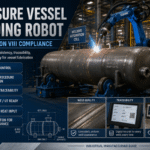
| Power & Pressure Equipment | Boiler tubes, pressure vessel saddles, metal plates | Circumferential, saddle-to-shell | ASME BPVC Section IX |
Fabricators processing 50 or more H-beams a shift have reported 35-45% reductions in cycle time after installing a ground rail welding robot to automate web-to-flange fillet welds. Savings are from two factors: the robot consumes a near-constant rate of travel that manual welders can’t match down a long seam, and the ground rail allows a 6-meter beam to be turned over mid-weld without repositioning.
All welds fabricated by the system must meet the relevant code. For steel buildings and industrial structures in the United States, this means AWS D1.1/D1.1M:2025 – the latest version of the Structural Welding Code for Steel. Eurocode projects submit to EN 1090 execution classes. Holding stable process variables — voltage, travel speed, wire feed — along a 12-meter weld is what makes code compliance repeatable.
✔ Where Ground Rail Welding Robots Excel
- Long, continuous welds on beams, columns or panels greater than 3 meters
- Repetitive weld patterns on similar structural members (H-beam lines)
- Multi-pass groove welds where consistent heat input matters across the full joint
- High-volume production where arc-on time directly drives throughput
⚠ Where They Are Not the Best Fit
- Short, 300 mm or less welds on small parts a fixed cell or cobot is more efficient to setup.
- Highly irregular one-off assemblies that resist offline programming
- Difficult access areas where a 15-18 m clear aisle is impractical
- Small-volume job shops with fewer than 5 similar parts a week
💡 Key Takeaway
ground rail welding robots offer the fastest return on investment in steel structure fabrication and shipbuilding – applications that involve long, repetitive seams and tight code requirements (AWS D1.1, EN 1090).
Ground Rail Welding Robot vs. Fixed-Position Robotic Welding Cell
Choosing between a ground rail system and a dedicated robotic welding cell is based on workpiece geometry, output volume, and floor space. Every dimension in the comparison below uses actual numbers, not generalizations.
| Dimension | Ground Rail Station | Fixed-Position Welding Cell |
|---|---|---|
| Working Envelope | 6–15 m linear travel + robot reach radius | ~2 m radius (robot reach only) |
| Max Workpiece Length | Up to 15 m single-pass; longer with rail extensions | Limited to fixture/positioner capacity (typically ≤3 m) |
| Programming Approach | Offline programming (Tekla/CAD import); teach-free for repetitive structures | Teach pendant primary; offline optional |
| Floor Space (12 m rail example) | 15–18 m × 5–6 m clear lane (including safety zones) | 4 m × 4 m typical (enclosed cell footprint) |
| Cycle Time on 6 m Fillet Weld | Single continuous pass; no repositioning stops | Requires 2–3 repositions (crane + re-clamp + re-reference) |
| System Cost (Turnkey) | $80,000 – $250,000 | $130,000 – $250,000 (pre-engineered) |
| Best-Fit Application | Long-seam structural steel, shipbuilding panels, bridge girders | Short-cycle parts: brackets, frames, sub-assemblies ≤1 m |
Cost of fixed-position cells is derived from the CLOOS NA 2025 robotic welding cell cost guide which prices pre-engineered turnkey cells at $130,000-$250,000 with a robot, power source, positioner, safety enclosure and controls. Ground rail stations sit in the same general price bracket but provide a very different working envelope.
Weld cost per meter tells a story that is easier to understand than the sticker price. On a 12m weld H-beam fillet, a ground rail station completes the weld in a single continuous pass. A fixed cell requires the workpiece to be repositioned two or three times — each repositioning cycles in the crane, re-clamps and re-references the weld start point. During a run of 50 beams, those cycles amount to hours of lost arc-on.
⚠️ Floor Space — Often Underestimated
You can’t fit a 12m ground rail in a 12 meter bay. You need an extra 3-6 meters of un-obstructed travel corridor to allow for robot overtravel at both ends plus the required safety zone perimeter. Watchout for ceiling height – the robot arm, when fully extended in an inverted mount, clears 3.5m above the rail. Measure before you order.
Get a Ground Rail Station Quote →
💡 Key Takeaway
A ground rail station can cost the same as a fixed cell but address a different problem. Choose ground rail if your workpiece longer than 3m, fixed position cell if your workpiece is short-cycle, high-volume small parts.
How to Select the Right Ground Rail Welding Robot Station

Designing a ground rail welding robot station is not a ‘pick from the catalog’ activity. Your configuration depends on what you weld, how fast you weld it, and what can physically fit in your facility. Use this six-point checklist to quickly determine if you need a simple to a complex solution
- ✔
1. Measure maximum workpiece length — Your longest beam or panel dictates the rail length. A 9-meter H-beam needs at minimum a 9 m rail, with 12 m preferred to allow robot overtravel without repositioning. Order the rail for your largest part, not your most common one. - ✔
2. Identify weld types and welding process — Fillet-only jobs can run with a standard MIG/MAG setup. Multi-pass groove welds on thick flange plates may require tandem-wire or a higher-duty welding machine. Confirm the power source amperage (350 A is typical; thicker plate may need 500 A). - ✔
3. Calculate throughput and ROI — Estimate annual weld volume in linear meters. Compare current labor cost against projected robot cycle time. With the average welder costing approximately $57,000 per year in direct wages, most ground rail stations reach ROI within 12–24 months at two-shift utilization. - ✔
4. Verify facility floor space and ceiling height — Add 3 meters beyond each rail end for overtravel and safety fencing. Check ceiling clearance for inverted or bracket-mounted configurations. A 12 m rail typically requires a 15–18 m × 5–6 m clear zone. - ✔
5. Evaluate programming requirements — If your shop uses Tekla Structures for steel detailing, confirm the robot’s offline software can import Tekla models natively. Teaching-free welding capability cuts programming time by 60–70% on repetitive structures — but only if the software supports your CAD format. - ✔
6. Specify environmental protection rating — Indoor clean-room fabrication needs IP56 minimum. Outdoor or dusty industrial environments call for IP67 on the lower joints (J3–J6) where debris accumulates. Under-specifying the IP rating leads to premature servo failure and unplanned downtime.
Having seen herds of them in 50+ countries over three decades of SPS projects the most common ordering mistake for me is ordering the rail for today’s work earlier tomorrow’s. Rail extension is feasible but 30-40% more expensive per meter when added after installation. If you plan to order a ground rail welding robot station, take into account rail length for future extension.
Request a Custom Configuration →
💡 Key Takeaway
Six factors influence the configuration: workpiece length, weld type, speed, and ROI ground space, programming compatibility, IP rating. Take the decision on the rail length first – rest is easy.
Frequently Asked Questions
How does the ground rail system improve a welding robot’s functionality?
View Answer
Linear travel along a ground rail gives a 6-axis robot a seventh axis, expanding its reach from about 2 meters to 6–15 meters. Long-seam joints get welded in one pass — no mid-weld stops, no distortion from arc restarts.
How much does a ground rail welding robot station cost?
View Answer
Turnkey ground rail welding robot stations generally fall in the range of $80,000 to $250,000, depending on rail length, robot brand, welding process (MIG/MAG, TIG, submerged arc), and peripheral equipment (laser tracker, gun cleaning station, safety enclosure). A 6 m single-robot station is at the low end; a 15 m dual- station with teach-free programming and 3D vision is toward the high end. ROI at 2-shift operation is generally 12-24 months.
How is the welding path programmed on a ground rail robot?
View Answer
Two main approaches. Teach-free offline programming imports a 3D model (Tekla, SolidWorks, or UG), automatically locates weld seams, and generates the robot path including rail travel coordinates — no manual jogging needed. Manual teach pendant programming is still used for one-off parts or when no CAD model exists, but it takes 4–8 hours per complex assembly compared to minutes with offline software. Most steel structure shops now default to the offline approach because each new beam variant only requires a file swap, not a full re-teach.
What is the lifespan of a ground rail welding robot?
View Answer
Robot arm: 80,000–100,000 operating hours (8–12 years single-shift, 5–7 years double-shift). Ground rail mechanism: 15–20 years with scheduled lubrication and periodic rail alignment. Consumables like contact tips, nozzles, and wire liners turn over every few hundred hours.
Can a ground rail welding robot be customized for specific workpieces?
View Answer
Yes. Virtually all parameters are customizable: rail length (6-15+ m), robot payload and reach, welding process (MIG/MAG, TIG, submerged arc), sensor type (2D laser line vs. 3D vision), and safety enclosure size. Some vendors also supply dual-station rail where two work zones share one rail – robot welds in one zone while an operator loads next workpiece in the other.
What safety features are included in a ground rail welding robot workstation?
View Answer
Standard safety features include light curtains along the rail enclosure perimeter, arc flash shields, emergency stop buttons at various access locations, collision detection in robot controller software, and fume extraction hoods or downdraft tables. Systems sold to U.S. must meet AWS D16.1M/D16.1:2018 – the robotic arc welding safety specification – which covers cell layout, guarding, and operator access.
About This Analysis
This paper was drafted by Zhouxiang’s welding automation engineering team, based on 30+ years and over 1,000 ground rail welding robot station projects in structural steel, shipbuilding, and heavy equipment manufacturing. Cost and ROI data cited are cross-checked against published industry sources including IFR, CLOOS, and AWS standards. Zhouxiang supplies the systems described – we are honest about that so readers can judge our first-hand field data accordingly.
References & Sources
- World Robotics 2025 Report — International Federation of Robotics (IFR)
- Steel Structure Welding Robot Market Outlook 2025–2032 — IntelMarketResearch
- Robot Offline Programming for Welding: No-Code Workflow — Visual Components
- Welding Seam Tracking and Inspection Robot Based on Improved YOLOv8s-Seg Model — PMC / National Institutes of Health
- AWS D1.1/D1.1M:2025 — Structural Welding Code for Steel — American Welding Society
- AWS D16.1M/D16.1:2018 — Robotic Arc Welding Safety — American Welding Society
- How Much Does a Robotic Welding Cell Cost in 2025? — CLOOS North America