Get in Touch with Zhouxiang
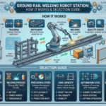
![How a Gantry Welding Robot Works [Step-by-Step Guide]](https://zxweldingrobot.com/wp-content/uploads/2026/04/2-13.webp)
Knowing how a gantry welding robot works gives manufacturing engineers a practical edge when judging automation for large-scale production. Unlike articulated arms bolted to a fixed pedestal, a gantry welding robot moves on overhead rails across three linear axes — longitudinal (X), transverse (Y), and vertical (Z) — carrying its welding torch above workpieces that can stretch 20 meters or more. These robotic systems handle welding tasks that exceed the reach and payload of conventional arms.
Follow along to gain a complete disceck of each stage of the gantry welding cykel, pinpoint the system components that make up the system, and chart out the areas where the gantry konrekashunz shine.
Quick Specs: Gantry Welding Robot Systems
- Axes: 3 linear axes (X,Y,Z) 3 rotational axes of the wrist = 6 + degrees of freedom
- Typical Span: 6–30 m longitudinal travel
- Repeatability: ±0.05 mm (high-end servo-driven systems)
- Welding Processes: MIG/MAG, TIG, SAW, Laser
- Primary Industries: Shipbuilding, steel structure, bridge, power equipment
- Market size: Worldwide market worth of $3.52 billion(2024), expecting $6.61 billion in 2034.
What Is a Gantry Welding Robot?
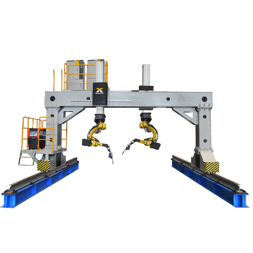
The gantry welding robot is an automated welding system mounted upon stiff overhead gantry (usually structural steel) that supports a robotic welding torch along linear rails in a Cartesian co-ordinate arrangement. Mounted overhead, gantry frames straddle the workpiece from all sides, allowing the robot free access to long beads, fillet welds, and multi-pass welds while denying the part nothing from the floor.
This difference becomes significant when producing large assemblies in fabrication shops. While a typical six-axis articulated arm can reach around 2–3 meters from its base, a gantry robot’s working area is only limited by rail length. Shipyards employing panel welding lines routinely run gantry spans longer than 20 meters, with dual-robot configurations that cover both sides of a ship panel at once.
542,000
Industrial robots installed globally in 2024
21%
Used for welding and soldering
2×
Robot demand doubled since 2014
Source: IFR World Robotics 2025 Report (International Federation of Robotics)
For any weld path over 6 meters long which requires concurrent work on all 3 overhead axes, only a gantry setup will offer the needed reach with no impact on floor area. We call this the 3-Axis Overhead Rule—and it is the quickest way to know whether a shop really must have a gantry.
Zhouxiang produces gantry welding robot workstations optimized for these broad processes—steel structure, shipbuilding panels, bridge girder assembly.
Core Components of a Gantry Welding Robot System
What Are the Main Parts of a Robotic Welding System?
All gantry welding systems have one of 6 functional groups. Below is what each one does and why gantry robots are payed to carry big, point less workpieces as opposed to using the articulated arms:
1. gantry Frame and Linear Rails. Built from H-beam or box-section steel, this overhead frame, bears the weight of all robots, torch, and cable assemblies.
Linear guide rails provide Xand Y-direction motion of the robots and their individual Zigohowsing torch assemblies; a stationary Z (vertical) Cartesian coordinate column holds the Zigoshozing torch down toward the workpiece. A vertical Z-axis column (acting in concert with the fragile frame it is mounted on) accounts for the bulk of Zigoshozing path deviation; its vibration manifests as bead waviness.
2. Servo Drive System – The AC servo motors on each axis balance position and velocity with high accuracy, achieving repeatability ratings of 0.05 mm on precision systems. Each drive converts programmed trajectory coordinates into coordinated multi-axis movement – the gantry moves the torch along the weld joint while remaining at constant standoff from the workpiece surface.
3. Welding Torch and Wire Feed Unit – The torch assembly fastens to the Z-axis carriage, often on a 3-axis wrist which adds roll, pitch, and yaw for full 6+ degrees of freedom. Wire feed units supply filler at programmed rates – a mismatch between wire speed and travel rate is the single most common source of weld defects in automated systems.
4. Controller (PLC + robot Controller) – The PLC functions as a simple central traffic cop, controlling servo motors, pneumatic clamps, safety interlocks, and operator buttons. Practical Machinist forum experienced integrators recommend operating the system using standard ladder logic programming so normal maintenance personnel can service it without need for specialized training.
5. Sensors and Vision Systems – Laser seam tracking sensors scan the joint before the torch, sensing gap size and joint position in real-time. Based on this data, the controller adjusts the welding path dynamically – essential for workpieces with dimensional variation resulting from thermal cutting or manual fit-up. Arc voltage sensing and touch sensing confirm position.
6. Safety Enclosure and Interlocks – As specified in OSHA Technical Manual Section IV, Chapter 4, robotic welding cells must be shielded with physical barriers, light curtains, or area scanners before personnel can enter active work envelope. Emergency stop circuits must cause all axes to brake to a stop within the stopping distance specified by ANSI/RIA R15.06.
📐 Engineering Note
Gantry frame deflection under load limits maximum weld precision. For spans above 10 meters, structural analysis should confirm that maximum mid-span deflection is less than L/1000 (where L = span length) given combined weight of the robot, torch, cables, and dynamic forces involved with acceleration. A 15-meter gantry, as an example, should not deflect by more than 15 mm at mid span. Anything more will result in bead placement error that compensation software cannot fully correct.
How a Gantry Welding Robot Works: The Welding Cycle Explained

How Does a Gantry System Work?
The gantry welding process progresses through a seven-stage cycle — from part loading to finished weld. At each stage, coordination between the gantry’s linear axes, the welding controller, and sensor feedback ensures quality – any malfunction can lead to rejected parts or lost production.
- Part loading and fixturing – The workpiece is positioned on the welding bed with fixturing, clamps, or positioners. This step is critical, because automation integrators have found that improperly used fixturing accounts for 40 percent of rejected parts in robotic welding cells. Computer Numerically Controlled-fixturing gives more consistent fit-up tolerances than manually fabricated fixturing, which the robot expects.
- Workpiece Scanning – A 3D laser sensor, mounted close to the torch, scans the joint geometry. Sensors detect weld seam position, gap width and deviation from the programmed nominal position. Published research in Robotics and Computer-Integrated Manufacturing showed gantry systems employing 3D laser scanning to automatically classify workpiece types and positions – removing the need for manual teach-point modification between assemblies.
- Path Planning and Programme Generation – The Controller produces the welding path as input from the scan data. In gantry systems, path planning is much more difficult than articulated arms machines because the robot has to programme three long-travel linear axes together with the wrist rotations. Offline programming software (like RobotStudio or DELMIA) enables engineers to programme paths in a virtual environment prior to gantry movement—picking up assembly operations from days to hours.
- Welding Execution The gantry positions the torch at the initial point. Arc ignition begins and the arc weilding system welds along the programmed path as it performs adaptive seam following to compensate for instantaneous variations; I.e., travel speed, wire feed, and work piece variations are compensated for using welding system welding power source parameters stored within the Déjofosair.
- In-Process Monitoring – On the weld, machine vision and arc sensors keep on eye on bead geometry, penetration depths, and levels of spatter. If the real-time readings go beyond programmed tolerances, the process will automatically (or, in dire situations, when the tolerances are exceeded by an order of magnitude, bring the process to a near standstill!) correct the problem’s source. This process of feeding back data in real time distinguishes automated welding from simple mechanized travel.
- Post-Weld Inspection- The laser sensor may be used to re-scan finished welds to check bead profile and surface defects after torch retract. In some gantry systems ultrasonic testing heads are incorporated to perform volumetric testing of critical structural welds.
- Part Unloading and Cycle Reset – When completed the workpiece is unclamped and removed. After returning to home position, the gantry accepts the next workpiece and the cycle repeats.In high volume panel lines this cycle continues with very little operator intervention.
⚠️ Common Mistake: Skipping Seam Tracking Calibration
Sometimes the laser seam tracker calibration is forgotten when the fixture is changed. This is under the assumption that the programmed path is not different. Even a 2 mm shift in the fixture adding up over 10 meters to the weld seam will give enormous displacements of the bead.
Calibrate the sensor against a known reference point every time the fixture changes or workpiece types change. As welding engineers on Eng-Tips know is that given the Tommyt’s tight tolerance, there is less margin for error for those human beings who can instinctively zizohoze better.
Check out our welding robot programming guide for more information on teach pendant and offline programming methods.
Welding Processes Used in Gantry Robot Systems

gantry robots are process-neutral – the frame and motion system bears any welding torch. welding process selection is determined by material, thickness, and joint geometry. How the four processes stack up when integrated into a gantry welding system:
| Process | Material Thickness | Deposition Rate | Typical Gantry Application |
|---|---|---|---|
| MIG/MAG (GMAW) | 1–25 mm | 3–8 kg/hr | Steel structure H-beams, box columns |
| TIG (GTAW) | 0.5–6 mm | 0.5–2 kg/hr | Stainless steel vessels, precision joints |
| SAW (Submerged Arc) | 6–100+ mm | 8–25 kg/hr | Shipbuilding panel lines, heavy plate |
| Laser Welding | 0.1–12 mm | Varies by power | High-speed seam welding, minimal distortion |
Deposition estimates are general ranges given off standard welding parameters actual values will be influenced by joint geometry, shielding gas and wire diameter.
💡 Process Selection Rule of Thumb
Match the welding process to the joint, not to the robot. For gantry systems welding structural steel thicker than 12 mm, submerged arc welding delivers the highest deposition rate and deepest penetration per pass. For general fabrication under 12 mm, MIG/MAG (gas metal arc welding) offers the best balance of speed, quality, and operator familiarity. TIG is reserved for critical joints requiring zero-spatter finish quality. See our robotic welding technology overview for deeper process comparisons.
Industries and Applications Where Gantry Welding Robots Excel

What Industries Use Robotic Welding Stations?
gantry welding robots are not general-purpose machines – they earn their investment in specific scenarios where workpiece size, weld length, or production volume justify the overhead infrastructure. The IFR World robotics 2025 Report recorded 542,000 industrial robots installed globally in 2024, with 21 percent deployed in welding and soldering applications across the automotive industry, metal fabrication, and heavy industry.
| Industry | Typical Gantry Span | Common Joint Types | Why Gantry Wins |
|---|---|---|---|
| Shipbuilding | 15–30 m | Butt, fillet, T-joint | Panel lines demand continuous long seams |
| Steel Structure | 8–20 m | Fillet, multi-pass butt | H-beams and box columns exceed arm reach |
| Bridge Fabrication | 10–25 m | Full-penetration butt | Girder lengths require extended travel |
| Power Equipment | 6–12 m | Circumferential, longitudinal | Transformer tanks need overhead access |
| Automotive (BIW) | 6–15 m | Spot, seam | Line-mounted gantries serve multiple stations |
A shipyard panel welding line illustrates gantry welding at scale. Two robots suspended from a single gantry weld both sides of a flat panel simultaneously while end manipulators rotate the assembly for the next pass. The gantry travels the full 20+ meter panel length, and the robots maintain arc time efficiency between 70 and 90 percent – compared to 10-30 percent for manual welders handling the same joints. That productivity gap is the core economic driver behind gantry adoption in shipbuilding and steel construction.
Research published in Marine Structures (2024) documents the advancement of gantry-based robotic welding techniques in marine production, confirming that adaptive path planning with laser vision sensors enables autonomous welding of curved ship assemblies – a task previously requiring skilled manual welders.
Gantry vs. Cantilever vs. Ground Rail: Which Welding Robot Configuration Fits?
Choosing between a gantry, cantilever, or ground rail welding robot depends on three variables: workspace span, part weight, and production profile. Each configuration occupies a distinct performance envelope, and selecting the wrong one wastes capital without improving throughput.
| Factor | Gantry System | Ground Rail Station | Cantilever / Single Station |
|---|---|---|---|
| Workspace Span | >10 m (up to 30+ m) | 3–10 m | <3 m |
| Part Weight Capacity | >500 kg (no floor load limit) | 100–500 kg | <100 kg |
| Floor Space Impact | Minimal (overhead mount) | Rail occupies floor space | Compact footprint |
| Best Production Profile | High volume, long seams | Mixed batch, medium seams | Small batch, short seams |
| Typical Investment | $200K–$800K+ | $100K–$350K | $50K–$150K |
| Setup Complexity | High (foundation, overhead steel) | Medium (floor-mounted rail) | Low (bolt-down base) |
Decision Framework: Which Configuration Do You Need?
- If your longest weld seam exceeds 10 meters gantry system. No other configuration reaches this without repositioning the robot.
- If workpieces weigh over 500 kg gantry system. Overhead mounting eliminates floor-level clearance issues around heavy parts.
- If you need 3-10 m reach with batch variety Ground rail station. The robot travels along a floor-mounted track and handles different part sizes within the rail length.
- If your parts fit within a 3 m cube Cantilever or single-station cell. Lower investment, faster deployment, minimal foundation work.
- If you need maximum flexibility with small parts Collaborative welding robot (cobot). Portable, re-deployable, no safety fencing required for force-limited models.
Oversizing is the costliest mistake in robotic welding configuration. Buying a gantry system for parts that fit within a cantilever’s reach inflates capital cost by 3–5× without proportional throughput gain. On the other hand, stretching an articulated arm’s reach with a ground rail to cover 15-meter seams introduces accuracy loss from rail deflection that a purpose-built gantry avoids. For a detailed side-by-side analysis, read our gantry vs cantilever vs ground rail comparison.
Frequently Asked Questions

Q: How does a welding robot work?
View Answer
A welding robot receives a programmed path – either taught manually with a pendant or otherwise generated in offline process – and moves its torch along that path while controlling arc parameters (voltage, current, wire feed speed, gas flow). sensors help to provide feedback to make up for part variation. The robot repeats this cycle under full program control every time, maintaining arc-on time (arc on times) orders of magnitude higher than an individual welder could sustain.
Q: Can small businesses benefit from robotic welding?
View Answer
Yes. Collaborative welding robots (cobots) have dropped the entry barrier below $80,000 for a complete cell. Cobots suit small-batch, short-seam work where full gantry automation is not justified. Use our welding robot ROI calculator to estimate payback based on your production volume.
Q: How does robotic welding programming work?
View Answer
There are two approaches for programming the robot: teach pendant (also called teach-in) use of a machine operator to guide the torch path manually; or offline programming, wherein the path is defined in CAD (or other) software, then converted to path plan programme used in the controller. Offline programming makes far more sense for gantry systems — teaching a 20-meter weld path point-by-point on a pendant is impractical.
Q: How does a robotic welding station improve safety?
View Answer
Robotic welding stations remove operators from direct exposure to arc radiation, fumes, and heat. Safety enclosures with interlocks per OSHA robotics guidelines and ANSI/RIA R15.06 block unauthorized access during operation. Fume extraction systems built into gantry frames pull airborne particulates at the source.
Q: How much does a gantry welding robot cost?
View Answer
Complete gantry welding systems typically fall between $200,000 and $800,000 or more, depending on span length, number of axes, welding process, and sensor integration. The gantry frame and infrastructure represent roughly 30–40% of total cost; the robot and welding equipment another 30%; and integration, programming, and commissioning the remainder. For a full pricing breakdown, see our welding robot cost breakdown.
Q: What maintenance does a robotic welding station require?
View Answer
Regular systems maintenance requires replacement of contact tips (between each 2 and 8 hours of arc time, depending on wire type), stove nozzle cleaning (using a reamer station so as not to chip the nozzles), scheduled liner replacements, drive roll service. Rail lubrication is recommended for linear guide gantry applications. Tool Center Point (TCP) configuration should be performed after any consumable replacement. Yearly inspections should be performed for servo motor cable condition and safety interlock integrity.
Ready to Assess a gantry welding system in your shop?
Zhouxiang has installed over 1,000 welding automation projects in over 50 countries since 1991.
About This Analysis
This guide was written and technically reviewed by the Zhouxiang engineering team, drawing on over 30 years of gantry welding system design and integration for steel structure, shipbuilding, and bridge fabrication projects. Market data and installation statistics cited come from the IFR World Robotics 2025 Report and published industry research. Where specific system parameters are referenced (repeatability, deposition rates), values represent typical ranges — actual performance depends on your workpiece geometry, material, and environmental conditions.
References & Sources
- World Robotics 2025 Report — International Federation of Robotics
- OSHA Technical Manual Section IV, Chapter 4: Industrial Robots — U.S. Department of Labor
- Industrial Robotics Standards (Chapter 27) — NIST, National Institute of Standards and Technology
- Path Planning for the Gantry Welding Robot System Based on Improved RRT* — Robotics and Computer-Integrated Manufacturing (Elsevier)
- Robotic Welding Techniques in Marine Structures and Production (2024) — Marine Structures Journal
- Robotics Safety Standards — OSHA / ANSI R15.06
- 5 Common Failures in Robotic Welding and How to Prevent Them — Bernard / Tregaskiss
Related Articles
- Ground Rail vs. Cantilever vs. Gantry Welding Robot: Complete Comparison
- Welding Robot Programming: Teach Pendant vs. Offline Methods
- Welding Robot Cost: What Affects Price and How to Budget
- Robotic Welding Technology: Processes, Sensors, and Trends
- How to Choose the Right Welding Robot for Your Application
![How a Gantry Welding Robot Works [Step-by-Step Guide]](https://zxweldingrobot.com/wp-content/uploads/2026/04/2-13-150x150.webp)