Get in Touch with Zhouxiang

Pipe Spool Welding Robot for ASME B31.1 Projects

Contents
show
Power Piping Fabrication Guide
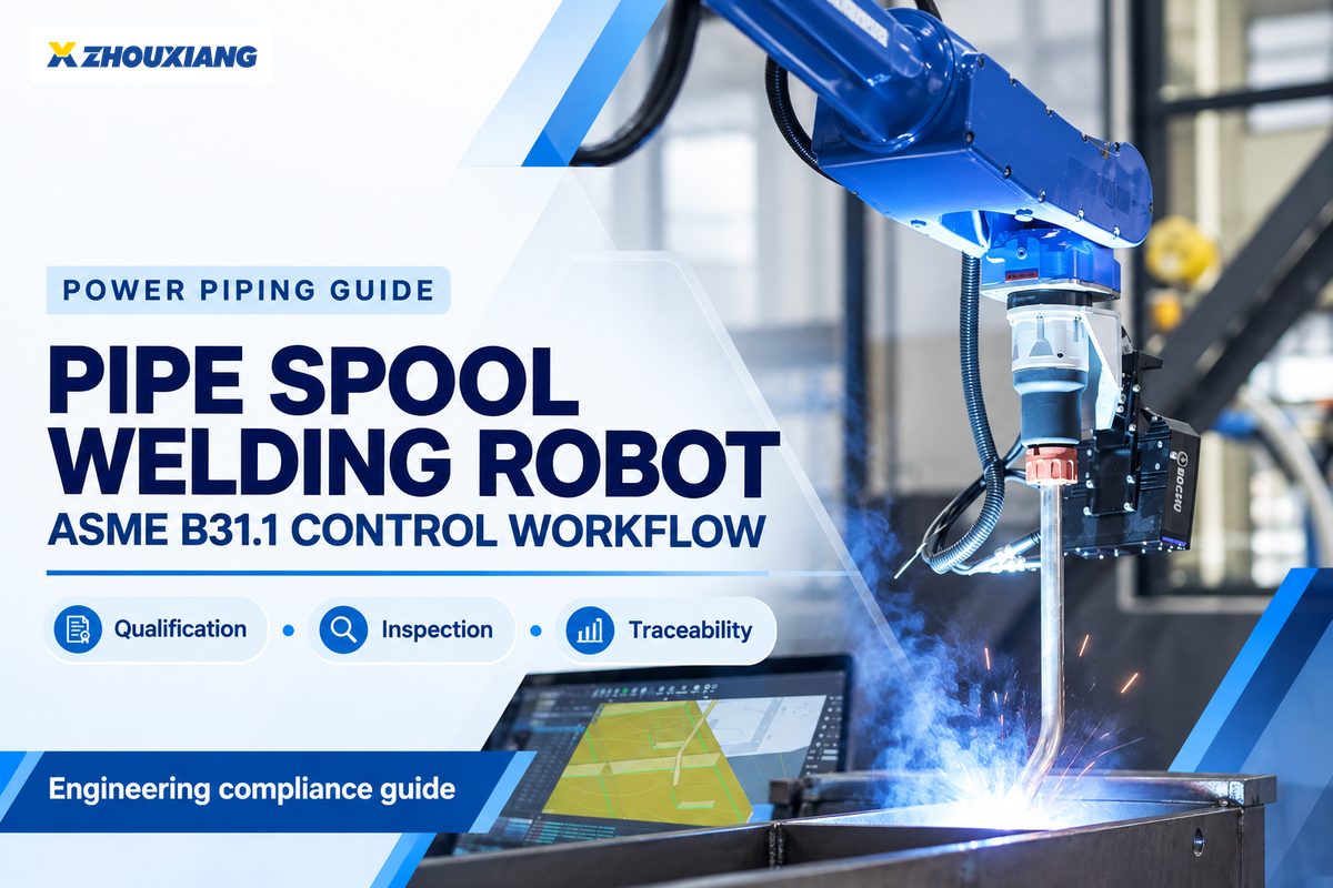
A pipe-spool welding robot can produce welds for a project that invokes ASME B31.1; in this guide, robotic welding systems means the complete cell around the industrial robot and robotic welding machine. However, the robot itself is not “code approved,” regardless of how robot manufacturers describe the equipment. Acceptance depends on the project’s adopted requirements, qualified welding procedures and personnel, controlled production, required examination, and a traceable release record and, when claimed, evidence of improved weld quality.
Important: This guide is an implementation framework, not a substitute for the purchased code, the engineering design, the owner’s specification, or the project quality plan.
Can a Pipe-Spool Welding Robot Comply With ASME B31.1?
Yes—when the welding operation is part of a qualified, controlled, and accepted fabrication system. The useful question is not “Is this robot B31.1 certified?” It is “Can this fabricator show that every applicable requirement is translated into a controlled production step and verifiable record?”
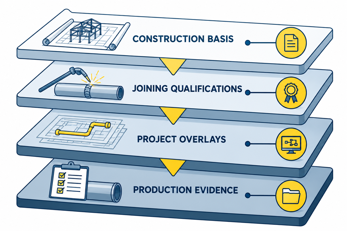
Think of the answer as a Four-Layer Compliance Stack:
- Construction basis: The adopted edition of ASME B31.1 and the engineering design establish the project’s power-piping requirements.
- Joining qualifications: The applicable ASME Section IX rules support procedure and personnel qualifications.
- Project overlays: owner specifications, jurisdictional requirements, contracts, drawings, inspection plans, and service conditions may add controls.
- Production evidence: The fabricator must maintain the actual spool, WPS, robot program, personnel, materials, examination, repair and release records connected.
This differentiation is relevant because a capable cell can still be used incorrectly. Conversely, mechanized or automatic production can be accepted when its qualified ranges, responsibilities, and evidence are managed. ASME’s public resources describe B31.1 in the broader context of power-piping design, materials, fabrication, examination, and testing, while its Section IX publication addresses welding, brazing, and fusing qualifications. ASME1, 2
Do not combine the qualification records. A qualified WPS and its supporting PQR address the procedure; the applicable welding-operator performance qualification addresses the person operating machine or automatic equipment. The project team should also verify which automation variables are applicable to its classification and the edition adopted. A qualification program cross-walk cannot be substituted.
Define the Code Boundary Before You Program the Robot
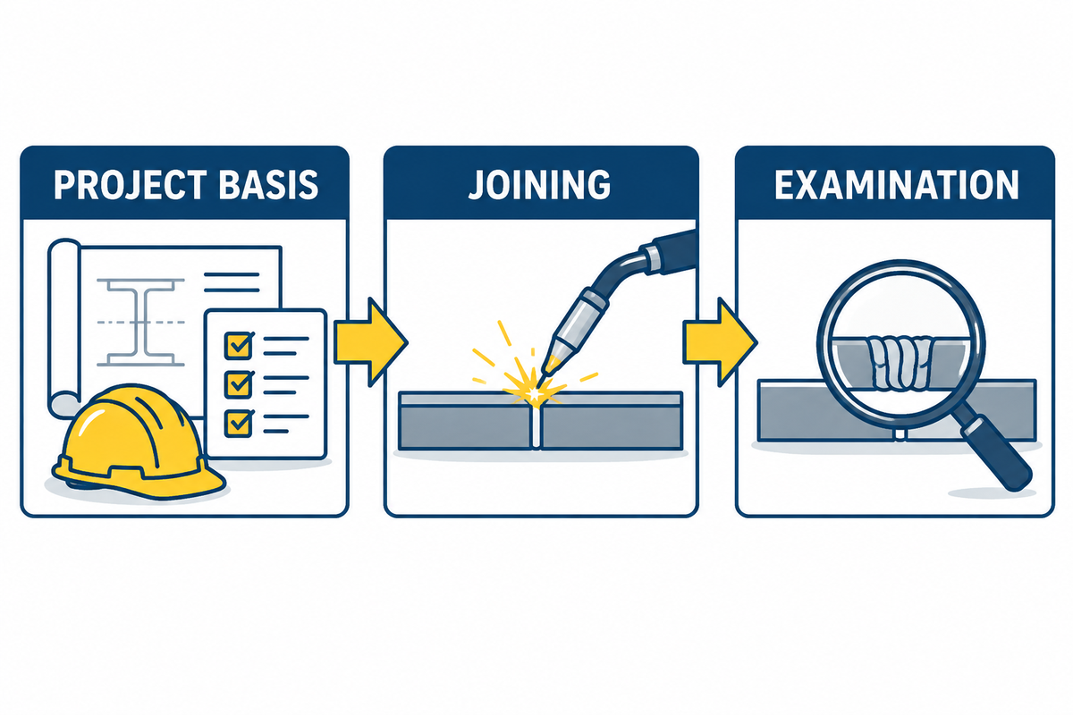
Premature programming leads to repeated effort. Develop a Code Applicability Matrix prior to selecting a weld schedule or constructing a production program. ASME’s B31.1 overview provides the public scope reference for that project-specific matrix.
| Control category | Question to resolve | Controlled output |
|---|---|---|
| Project basis | Which code edition, addenda, owner documents, and jurisdiction apply? | Approved applicability register |
| Design | Which lines, materials, wall ranges, joint details, and service conditions are in scope? | Released drawings and spool list |
| Qualification | Which WPS/PQR and personnel qualifications cover the proposed process and ranges? | Qualification matrix |
| Fabrication | Which fit-up, preheat, interpass, consumable, purge, and handling controls apply? | Route card or work instruction |
| Examination | What inspection, NDE, witness, acceptance, and repair rules apply to each joint? | Inspection and test plan |
| Release | Who can approve the first article, deviations, repairs, and final data package? | Named approval workflow |
| Automation | Which cell, welding machine, positioner, sensors, and software revisions are controlled? | Released equipment baseline |
| Change | Which changes require review, validation, or qualification-impact assessment? | Change-classification matrix |
One should not assume the latest published edition governs a given contract. Note the edition adopted by the project, and then have the responsible engineering and quality functions resolve conflicts before production.
Decide Which Spool Families Are Ready for Automation
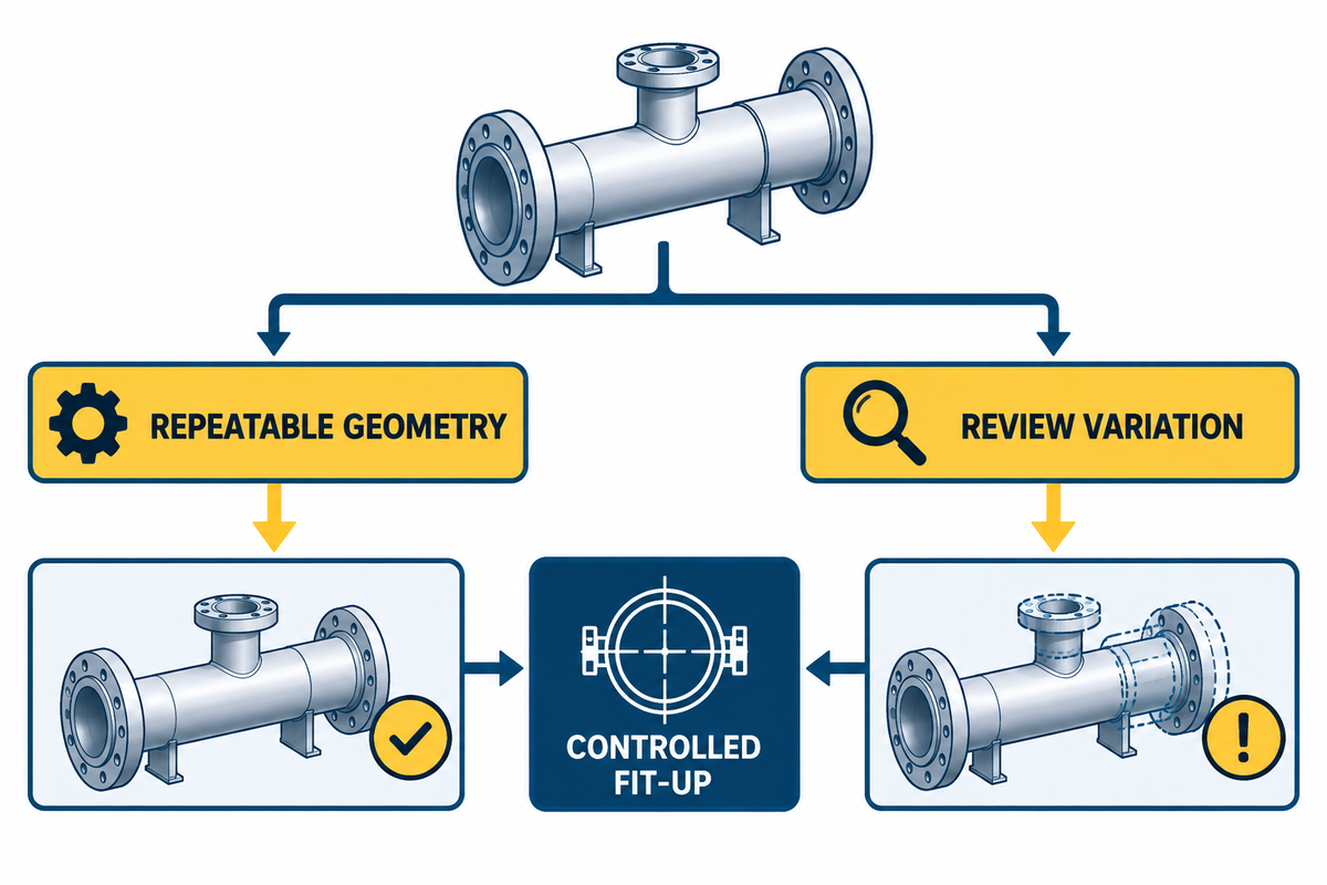
Diameter is a poor routing rule. A more appropriate Automation Screen determines whether the activity is stable, repetitive, and amenable to being performed by the entire cell.
| Screen | Robot-favorable signal | Review or alternate route |
|---|---|---|
| Geometry | Repeated joint family with controlled datum features | One-off geometry or unstable joint location |
| Fit-up | Preparation, alignment, gap, and tack strategy are repeatable | Variation exceeds the proven sensing and process window |
| Access | Torch, sensor, gas coverage, and inspection access remain clear | Branches, flanges, or fixtures obstruct the required approach |
| Motion | Positioner supports the load through the full coordinated path | Eccentric load, cable interference, or collision risk is unresolved |
| Volume | Programming and validation can be reused across a family | Programming effort outweighs the repeatable work |
| Evidence | Program, parameters, joint ID, and examination can be captured | The cell cannot produce the required traceability record |
Strong robot candidates may exist throughout a spool and one closure weld may require a specialized orbital method or be performed manually. Route by joint family and assembly sequence and not by forced method. Research on robotic piping welding emphasizes sensing, seam tracking, and adaptive control and path planning, and notes that the industry-scale verification remains an important open issue. Review3
The screening logic should be manufacturer-neutral. A welding system can combine a FANUC arm, Lincoln Electric power source, user-defined fixtures, and/or a supplier’s integrated package. Of those names, none indicate that the application is qualified. The same is true of TIG welding, GMAW, FCAW, and other selected processes. AI-assisted vision may improve location or monitoring, but productivity claims still require a representative shop test.
Build a WPS-to-Robot-Program Crosswalk
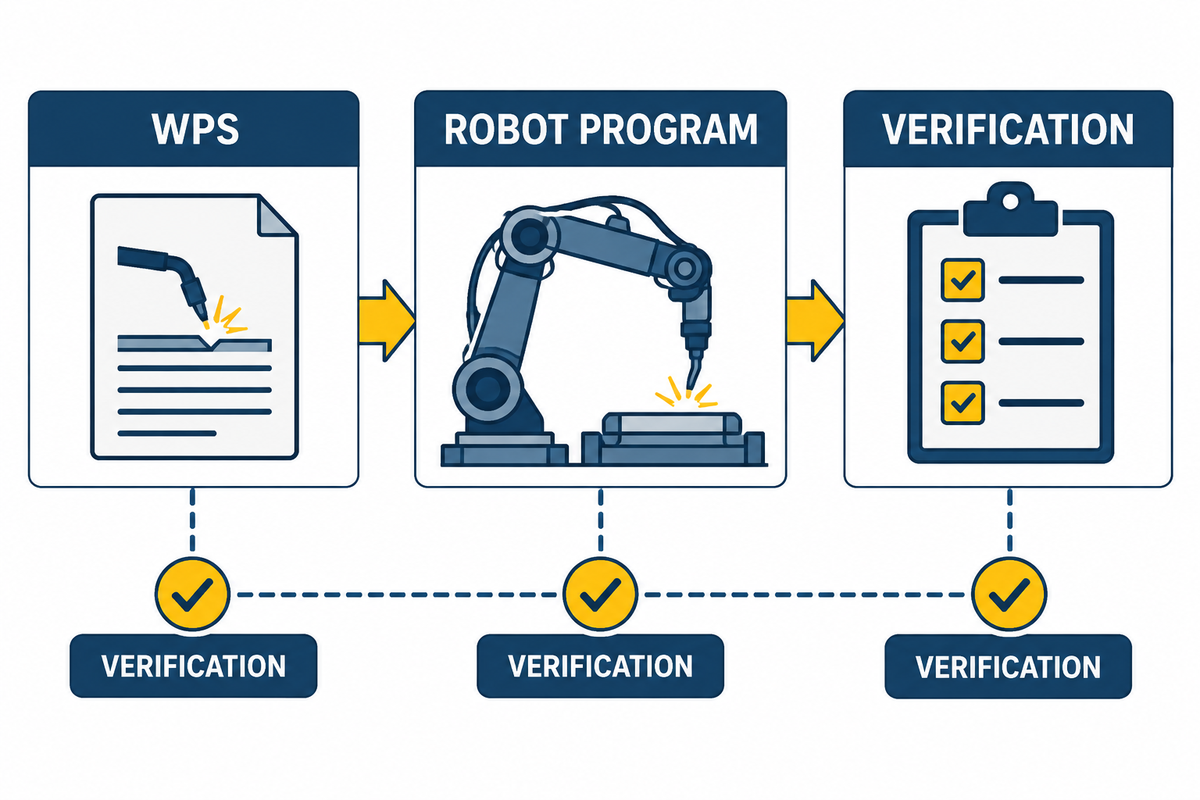
A robot program is an executable production recipe. It doesn’t replace the governing WPS or its qualification basis. Use a WPS-to-Program Crosswalk to illustrate how controlled welding requirements reach the cell. The ASME Section IX operator qualification form is a public reference for keeping personnel qualification distinct from program control.
- Identify the released WPS and supporting qualification record.
- Verify material groups, thickness and diameter ranges, joint configuration and position, process, filler and shielding are addressed.
- Identify controlled electrical and motion inputs and how they are implemented in the program.
- Define how preheat, interpass temperature, purge, consumable condition, and other non-programmed controls are measured and recorded.
- Assign a program ID, revision, approval status, cell, fixtures, and effective date.
- Restrict editing rights and preserve an auditable revision history.
The crosswalk should define what the control is, where it is implemented, how it is verified, and what happens if it changes. In general, it’s not advisable to copy a supplier’s demonstration program or demo to production without this review.
Control Fit-Up, Positioning, Seam Tracking, and Thermal Variables
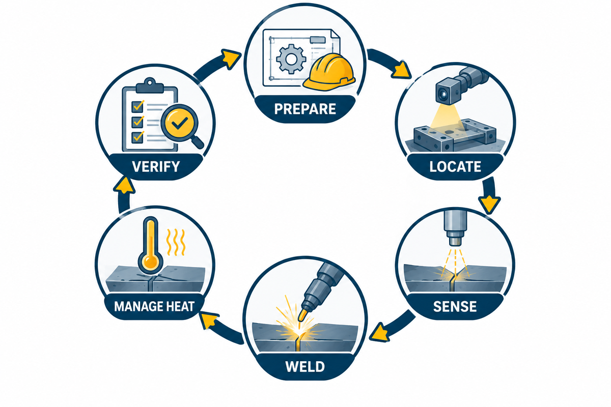
Stable robotic welding is a loop, not a single parameter set. The Six-Control Production Loop connects preparation, location, sensing, welding, thermal control, and verification.
- Prepare: verify end preparation, cleanliness, alignment, tacks, and any backing or purge arrangement.
- Locate: confirm repeatable datums and verify fixture and positioner status.
- Sense: evaluate seam-finding/tracking method, calibration, usable correction window, loss-of-track response.
- Weld: run released program with WPS controls and consumables, approved by the authority.
- Manage heat: measure required preheat and interpass conditions with specified method; control sequencing and cooling as the project requires.
- Verify: review alarms, exceptions, parameter records; assess bead condition, dimensions; and required examination before release.
Do not let a laboratory vision result serve as a cell-wide guarantee. For example, one published seam-recognition study reports high accuracy for its model and dataset; that result illustrates a research method, not dependable behavior across every material, arc condition, joint preparation, and production cell. Study4
Release the First Article Before Batch Production
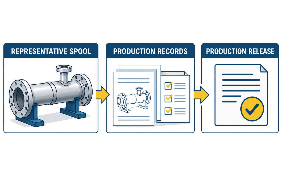
The first article should represent a declared spool family – not simply the easiest article to demonstrate. A useful first article release packet includes
- the reason for representing the proposed family, and the joint it covers;
- drawing, material, WPS, program, fixture, cell, personnel, and consumable identity;
- fit-up and readiness checks;
- dry-run, collision, sensor, interlock, and coordinated-motion checks;
- actual production records and deviations;
- required visual, dimensional, destructive, or nondestructive results;
- open items, repair disposition, approver, and production-release scope.
A passed first article should only release the defined combination and family. The release remains bounded by the project’s adopted B31.1 requirements and qualification records. It should not automatically release other materials, fixtures, sensors, access conditions or programs.
Separate Process Monitoring From Weld Examination and Acceptance
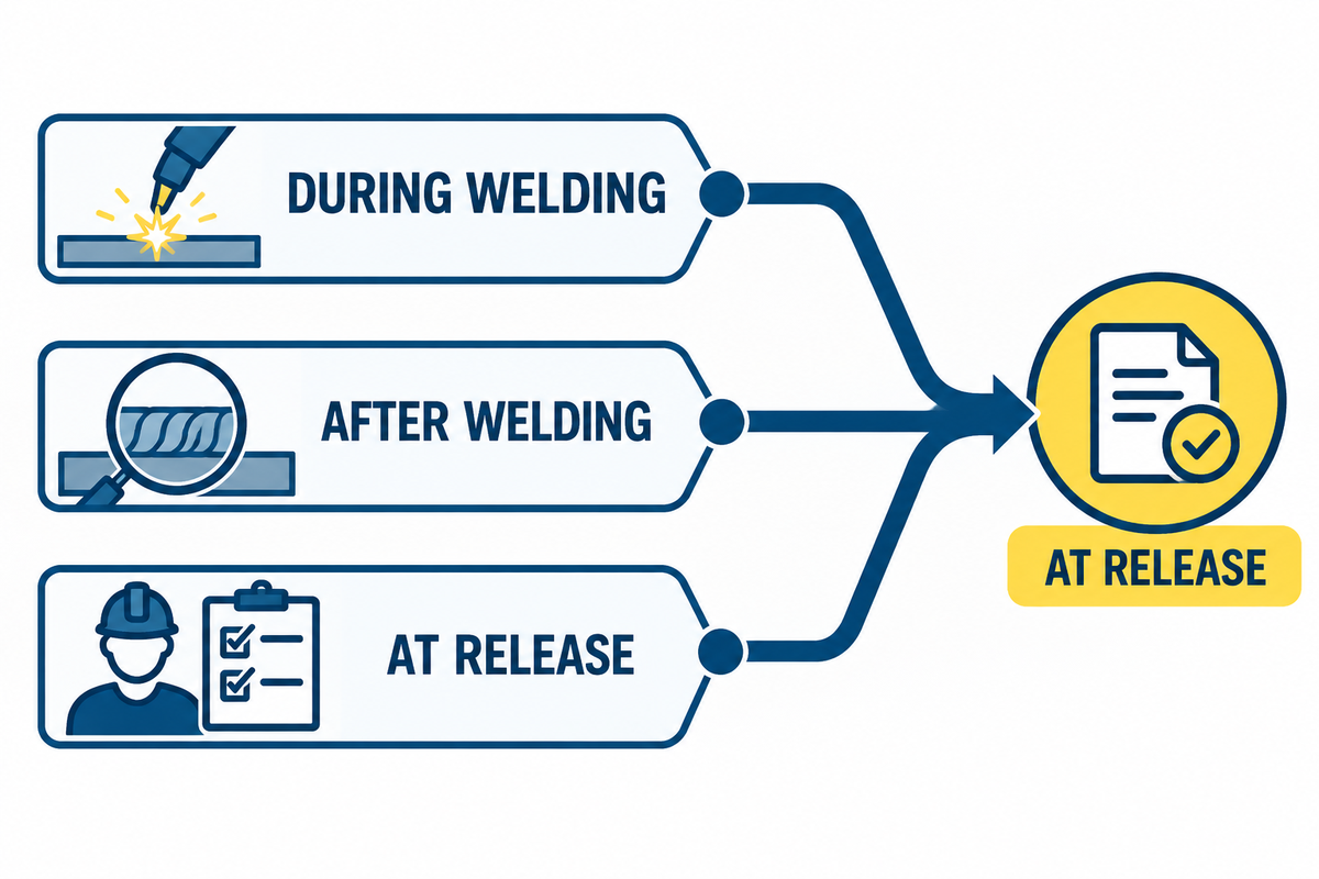
Current, voltage, wire feed, travel, and position data, along with vision and alarm data, help illustrate how a welding program ran. These data help with control, diagnosis and traceability. They do not automatically prove that a weld meets all of the acceptance criteria. The American Welding Society likewise treats automation and inspection as related but distinct evidence functions.
Use an NDE Hold-Point Map to delineate evidence roles.
Before weldingMaterial, drawing, fit-up, WPS, program, qualification, and readiness
During weldingProgram identity, process records, thermal checks, alarms, interruptions, and operator response
After weldingVisual and dimensional checks, specified NDE, result evaluation, and repair control
At releaseComplete record review, deviation closure, final status, and authorized approval
The methods, extent, timing and acceptance criteria for inspection in a given project are determined by the project’s inspection plan. Keep those outside a general robot specification.
Build a Weld-Level Traceability Record
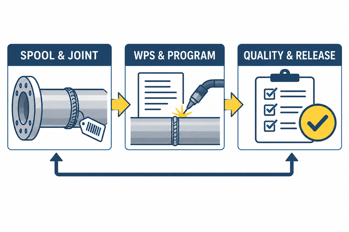
A good Weld Traceability Chain allows an auditor to move in both directions to determine the weld(s) and/or evidence associated with a released spool and to move from a program, or a batch of consumables, to all the affected joints.
| Record group | Minimum identifiers |
|---|---|
| Product | Project, line, spool, joint, drawing and revision |
| Materials | Base-material identity and heat/lot traceability; filler and gas identity as required |
| Method | WPS and revision; supporting qualification reference; applicable personnel status |
| Automation | Cell, robot, positioner, fixture, sensor setup, program ID and revision |
| Execution | Date/time, operator, parameter record, thermal checks, alarms, interruptions and deviations |
| Quality | Fit-up, VT, dimensional and specified NDE results; repairs and re-examination |
| Release | Final disposition, approver, date and data-package reference |
The volume of data provided is not the goal. The record should preserve identity, revision, exception, and disposition without making the reviewer reconstruct the story from unrelated files. That evidence chain supports the fabrication and examination context described in ASME B31.1.
Control Robot Program, Fixture, and Process Changes
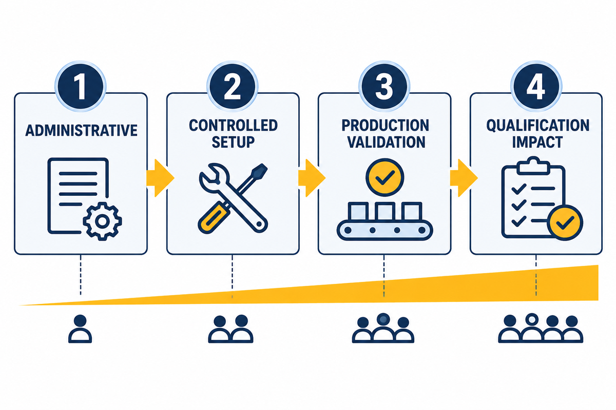
“The weld still looks the same” is not a change-control method. Use a Four-Zone Change Matrix to control changes.
| Zone | Typical change | Minimum response |
|---|---|---|
| 1 — Administrative | Metadata correction with no production effect | Controlled record update and review |
| 2 — Controlled setup | Approved consumable replacement, calibration, or like-for-like maintenance | Verification against the released setup and documented return to service |
| 3 — Production validation | Path, fixture, sensor, torch, sequence, or handling change that may affect execution | Engineering review and defined first-article or validation evidence |
| 4 — Qualification impact | Change that may leave qualified or project-approved limits | Stop; assess WPS/PQR, personnel, engineering, and project approval implications before release |
This four-zone structure is a management framework, not a code-defined taxonomy. The project team must set its own thresholds and approval authority. Practical robotic-welding guidance shows why this discipline matters: tool-center-point drift, incorrect paths, setup errors, and consumable problems can move the process away from its intended condition. Practical guidance5
Specify a Factory Acceptance Test for the Pipe-Spool Cell
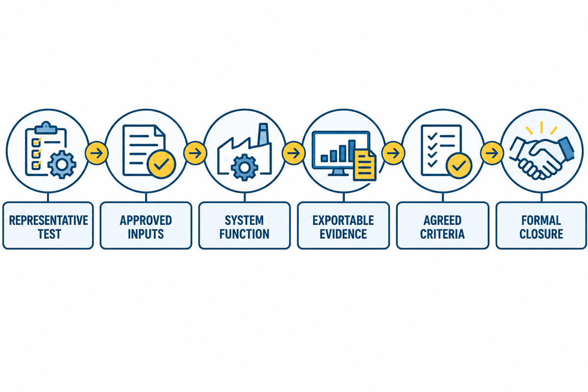
A typical demonstration shows that the machine can run. A project FAT should show that the cell, interfaces, controls and records can perform a declared representative test under agreed conditions. A general factory acceptance test reference helps distinguish a witnessed system test from production approval.
Build the FAT Evidence Checklist around six questions:
- What does the test represent in terms of spool families, materials, joint configurations, and process conditions?
- Are drawings, utilities, software, safety functions, instruments, WPS inputs and test pieces approved?
- Do robot, positioner, sensor, welding source, interlocks, extraction, data capture and recovery modes function cohesively?
- Evidence: Are measurements calibrated and are program, parameter, alarm, examination, and traceability records exportable?
- Are test methods and responsibilities, witness points, acceptance criteria, deviations and retest rules agreed to prior to the run?
- Closure: Are open items assigned, corrected, retested where necessary, and formally closed before shipment?
FAT completion should not be confused with approval of production welds. Production remains subject to the released procedures, actual spool conditions, inspection plan, and change controls.
Common Failure Modes and Stop Conditions
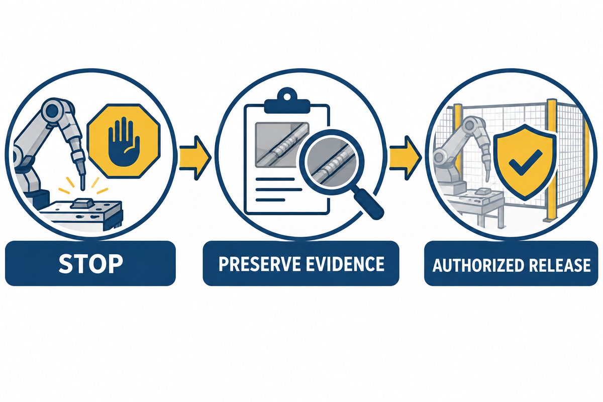
The process contains the conditions of the work being performed. Exceptions and variations should be recorded. Stop and contain if the process is leaving its defined state. Examples include lost seam tracking, unexpected positioner motion, collision or tool-center-point drift, unresolved fit-up variation, thermal-control excursions, purge loss, arc instability, missing data, unauthorized program revisions, or repeated repairs. Practical robotic-welding failure guidance provides examples of why these conditions need explicit stop rules.
Use a simple response: identify the affected joint range, preserve the evidence, correct the immediate condition, determine root cause, assess qualification and examination impact, then obtain authorized release before restarting. Do not “tune through” a problem until it looks acceptable.
Keep Robot-Cell Safety Separate From Piping-Code Acceptance
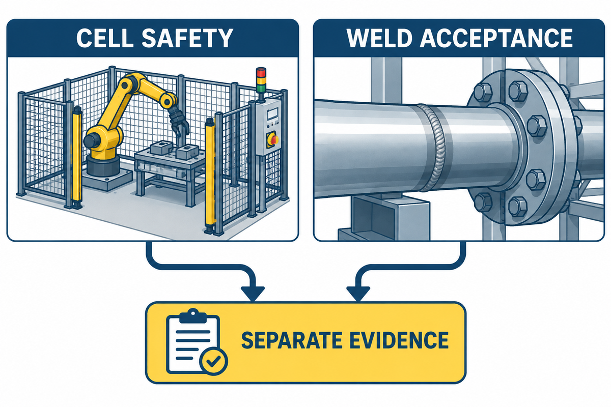
While the cell remains unsafe to operate or maintain, a weld can fulfill its quality requirements. The integration team needs an application-specific risk assessment covering the robot, positioner, tooling, arc, fumes, hot work, utilities, material handling, restricted spaces, and foreseeable intervention tasks.
Define the following: safeguarding, access control, emergency stops, safe recovery, lockout or hazardous energy control, ventilation and fume extraction, training, maintenance positions, and validation of safety functions. These will not be replaced by a B31.1 weld record. Treat them as a parallel acceptance stream with their own evidence and authorities. OSHA’s robotics overview notes that many robot accidents occur during non-routine conditions such as programming, maintenance, testing, setup, or adjustment.
Frequently Asked Questions
Does ASME B31.1 approve a particular welding robot?
No. A project does not become compliant because a supplier describes a robot as “B31.1 capable.” The project team must establish the adopted requirements, qualified procedures and personnel, production controls, required examination, traceability, and acceptance authority. Evaluate the cell by whether it can implement and document that controlled system.
Does robot programming replace a qualified WPS or operator qualification?
No. The WPS defines the approved welding procedure within its qualification basis; the robot program implements selected production instructions on a particular cell. They must have an explicit, revision-controlled crosswalk. Applicable personnel qualification and responsibility must also be confirmed from the adopted code and project documents. A program may be technically executable and still be outside an approved procedure or project control.
Can robot process data replace visual examination or NDE?
Not automatically. Process data reveal how monitored variables behave, and are therefore useful for control and traceability, as well as investigations. The role of evidence is different for visual examination, NDE, and acceptance evaluation. The inspection plan dictates which examinations are required, when they occur, who performs them, and how results are accepted.
What belongs in a robotic pipe-spool weld data package?
Connect the project, line, spool, joint, drawing revision, materials, WPS, qualification references, robot cell, fixture, sensor setup, program revision, personnel, consumables, production parameters, thermal checks, alarms, deviations, visual and dimensional checks, specified NDE, repairs, re-examination, and final release. The package must make every affected weld searchable when a material, program, fixture or examination record is changed.
The weld record is just one part of the dossier. Final turnover packages may require other documents such as component, subassembly and assembly, or complete system records, defined by the project. Align those records to weld data, rather than assuming a collection of joint logs is the entire compliance file.
Turn the Compliance Plan Into a Cell Specification
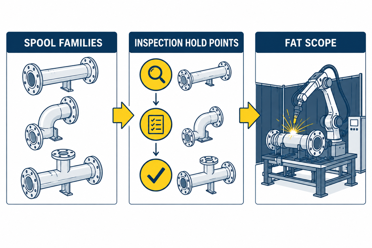
Prior to requesting a configuration, provide the supplier with a bounded input package, comprised of spool families, material and joint details; adopted code and project overlays; welding processes and qualification boundaries; fit-up and handling assumptions; inspection hold points; data and traceability requirements; interfaces; FAT scope; and change control requirements.
Cell architecture and equipment options, as well as project-specific information, are offered in the welding robot solution for the power industry. For a broader comparison of manual, orbital, and robotic methods, see the pipe welding guide. Information related to mainline and tie-in work in pipelines is provided in the pipe-line welding guide. Structural code-related information is provided in the AWS D1.1 robotic welding guide.
References & Sources
- ASME — B31 Piping and Pipelines.
- ASME — BPVC Section IX: Welding, Brazing, and Fusing Qualifications.
- Cajner H, et al. Robotic Welding Technologies for Intersecting and Irregular Pipes and Pipe Joints Toward Automated Production Line Integration: A Review. Applied Sciences. 2026;16(6):2974.
- Welding Seam Tracking and Inspection Robot Based on an Improved YOLOv8s-Seg Model. Sensors. 2024.
- Tregaskiss — Common Robotic Welding Failures and Prevention. Used for examples of practical failures, not for code requirements.