Get in Touch with Zhouxiang

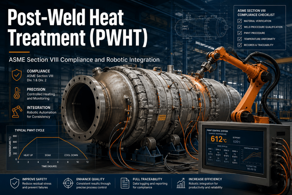
Post-Weld Heat Treatment (PWHT): ASME Section VIII Compliance and Robotic Integration
Contents
show
Post Weld Heat Treatment (PWHT): The Engineer’s Complete Guide to Code Compliance, Process Parameters & Inspection
What Is Post Weld Heat Treatment?
Post weld heat treatment (PWHT) is a controlled thermal process applied to a welded assembly after welding is complete. The assembly is heated to a specified temperature – always below the lower critical transformation temperature (Ac1, approximately 720-730C for carbon steel) – held at that temperature for a defined period, then cooled at a controlled rate.
The distinction matters: PWHT does not re-melt the weld or alter the weld geometry. It operates entirely in the solid state, allowing the steel’s atomic lattice to relax, redistribute locked-in stresses, and in some materials, temper a hard microstructure into a tougher one. The welding process deposits heat in a highly concentrated, non-uniform pattern – heat treatment after welding corrects the metallurgical consequences of that asymmetry. It is an engineering precision task, not a simple “heat and cool” operation.
Temperature Range
595 – 770 °C
Hold Time
1 hr / 25 mm (min 30 min)
Heating Rate
Max 400°F/hr ÷ wall thickness
Max Temp Differential
139 °C (250 °F) during soak
Process Standard
ASME UCS-56 / B31.1 / B31.3
Residual stress reduction is the primary goal of post welding heat treatment. Secondary goals include improving toughness and ductility in the heat-affected zone (HAZ), softening hard martensitic microstructures, and driving out diffusible hydrogen that accumulated during welding. All three objectives reduce the risk of in-service cracking.
Why Welding Creates Residual Stress
When a welding arc heats metal to 1,500C or higher, the surrounding base material stays relatively cool. Rapid cooling from welding temperatures then forces the hot weld metal to contract against the restraint of the cooler surrounding structure. The welded joint cannot contract freely – the surrounding material holds it. The result: the weld metal and the HAZ are placed in a state of residual tensile stress that can approach the yield strength of the material. For a mild carbon steel with a yield strength of 250MPa, the locked-in residual stress can reach 200-250MPa even in a perfectly made weld.
Two failure mechanisms are directly amplified by high residual stress:
- Hydrogen embrittlement: When welding, atomic hydrogen is produced from water (in the arc, coating, base metal). High internal tensile residual stress leads to expansion in the crystal lattice which opens up pockets where hydrogen readily moves and is stored at the grain boundaries, leading to the formation of hydrogen cracks (cold cracks or hydrogen-induced cracks, HAC), which can occur between hours and days after the completion of welding. This explains the importance of the control of inter-pass temperature to be kept above 200 °C between passes prior to any post weld heat treatment (PWHT).
- (i) Stress corrosion cracking (SCC). In wet H-S, chlorides, caustic, and CO-bearing process streams, SCC will occur on residual tensile stresses and will accelerate through cracks that are propagating in the HAZ of a micro-crack. SCC can occur only under three concurrent conditions; a material that is susceptible to attack, a corrosive environment, and a tensile stress.To prevent SCC the latter element must be removed by PWHT. In one study by TWI (2005) the PWHT of martensitic stainless steel girth welds at 650 °Celsius for 5 minutes at the time of welding led to a failure-free history as opposed to a number of service failures in the as-welded joints.
In case of high-chromium creep-strength-enhanced ferritic (CSEF) steels like P91, the as-welded HAZ is transformed almost 100% to untempered martensite after cooling down. The hardness of the HAZ at this point – generally 350-420HV – is way above the ASME allowable value of 250HB and embrittlement at service temperatures will not be an assumption but nearly a fact.
PWHT Code Requirements: What ASME and AWS Actually Mandate
The enduring Fabrication Shop Myth – ” all carbon steel welds over 12mm require pwht”. This is unequivocally not the case for any major code. There are codes to follow, materials groups to take into account as well as whether preheat was applied during the weld process prior to postweld heat treating!
The 38 mm Rule (ASME Section VIII)
ASME Section VIII Div.1 (pressure vessels) states PWHT is required for P-No.1 carbon steel with a thickness over 32mm (1.25 inches) unless pre-heating is performed. This “rule” extends to 38mm (1.5 inches) if the fabricator uses pre-heating in conjunction with a minimal pre-heat temperature of 93°C (200°F).
⚠ The 38 mm Rule Has Conditions
This 38mm exemption is valid only for P-No. 1 carbon steels ASME section VIII. A different code, a different material (P91), a different operating environment (NACE/ISO 15156 (sour service)) will induce different criteria (very often more stringent). Consult always the applicable code for your services.
This 38mm exemption is valid only for P-No. 1 carbon steels ASME section VIII. A different code, a different material (P91), a different operating environment (NACE/ISO 15156 (sour service)) will induce different criteria (very often more stringent). Consult always the applicable code for your services.
PWHT Thresholds by Code and Material Group
| Code / Standard | Material / P-No. | PWHT Mandatory Threshold | Notes |
|---|---|---|---|
| ASME Sec. VIII Div. 1 | P-No. 1 (Carbon Steel) | >32 mm (no preheat); >38 mm (with 93 °C preheat) | Most common vessel fabrication threshold |
| ASME B31.1 Power Piping | P-No. 1 (Carbon Steel) | >19 mm (¾ inch) | Lower threshold due to cyclic thermal service; reduced to 16 mm with preheat |
| ASME B31.3 Process Piping (pre-2014) | P-No. 1 (Carbon Steel) | >19 mm (¾ inch) | Same base threshold as B31.1 |
| ASME B31.3 Process Piping (2014+) | P-No. 1 (Carbon Steel) | Fully exemptible at all thicknesses | Requires 95 °C (200 °F) preheat for >25 mm; multi-pass welds for >5 mm. No PWHT needed if conditions met. |
| ASME Sec. I / B31.1 | P-No. 5B (Grade P91) | Mandatory — ALL thicknesses | No exemption. 730–770 °C, 2 hr minimum. Temperature uniformity ±30 °C. |
| AWS D1.1 Structural | Carbon & low-alloy steels | Procedure-dependent, not universally mandatory | WPS dictates; stress relief sometimes required per project specification |
Another change that process piping fabricators can especially celebrate with the 2014 revision of the ASME B31.3 is the ability to forego required PWHT for the welding on a P-No.1 carbon steel piping system by implementing controlled preheat at the weld. Exceptions apply to the sour service piping applications (where NACE/ISO 15156 hardness requirements will likely still mandate PWHT), and applications outside the P-No.1 category.
For welding procedure specification compliance, see our guide on Welding Procedure Specifications — what engineers must document.
PWHT Temperature and Hold Time: Reference Tables
Each post weld heat treatment has three controls: the temperature of soak range, a minimum hold time at temperature and allowable heat up / cool down rates. Each of the above, if incorrect, can have a far worse effect than no PWHT.
Material-Specific PWHT Parameters
| Material Grade (ASME) | Alloy Designation | PWHT Temp Range | Min Hold Time | Max Cooling Rate |
|---|---|---|---|---|
| P1 / P2 | Carbon steel / 0.5Mo | 595 – 720 °C | 1 hr per 25 mm (min 30 min) | Furnace or controlled |
| P11 / P12 | 1.25Cr–0.5Mo / 1Cr–0.5Mo | 680 – 730 °C | 1 hr per 25 mm (min 30 min) | Furnace or controlled |
| P22 | 2.25Cr–1Mo | 680 – 730 °C | 1 hr per 25 mm (min 30 min) | Furnace or controlled |
| P5 / P9 | 5Cr–0.5Mo / 9Cr–1Mo | 730 – 760 °C | 1 hr per 25 mm (min 30 min) | Furnace or controlled |
| P91 | 9Cr–1Mo–VNb (CSEF) | 730 – 770 °C | 2 hr minimum | Max 80 °C/hr above 400 °C |
| P92 | 9Cr–0.5Mo–2W (CSEF) | 730 – 770 °C | 2 hr minimum | Max 80 °C/hr above 400 °C |
What temperature is used for PWHT of carbon steel?
The ASME codes specify holding temperature range for P-No.1 carbon steel to be 595-720C (1,100-1,330F). The industry application following ASME UCS-56 most often holds around 1,150F 50F (621C 28C) to center in practice.
⚠ The Ac1 Ceiling — Why Higher Temperature Is Not Better
Exceeding approximately 720 °C for carbon steel crosses the Ac1 transformation temperature — the point at which steel begins converting back to austenite. Partial re-austenitization causes the HAZ to reform and harden during rapid cooling, potentially creating a worse microstructure than before treatment. For P91, exceeding 790 °C (the maximum safe tempering temperature) permanently destroys the fine M23C6 carbide dispersion responsible for creep strength — damage that cannot be reversed without a full renormalize-and-temper cycle.Discipline of maximum temperature is just as important as minimum temperature discipline.
Exceeding approximately 720 °C for carbon steel crosses the Ac1 transformation temperature — the point at which steel begins converting back to austenite. Partial re-austenitization causes the HAZ to reform and harden during rapid cooling, potentially creating a worse microstructure than before treatment. For P91, exceeding 790 °C (the maximum safe tempering temperature) permanently destroys the fine M23C6 carbide dispersion responsible for creep strength — damage that cannot be reversed without a full renormalize-and-temper cycle.Discipline of maximum temperature is just as important as minimum temperature discipline.
The heating rate per the ASME UCS-56 requirement for this is 400F/hr (222C/hr) maximum divided by the largest wall thickness to 3 inches (50mm) where 400F/hr (222C/hr) remains the absolute upper limit for thin sections. This would limit the heat-up rate of this 2 inch (50mm) thick shell to no more than 200F/hr (111C/hr). The hot and cold temperature difference across the entire assembly shall not exceed 250F (139C) during soak.
Four Types of Post Weld Heat Treatment Compared
PWHT isn’t a treatment, it’s a series of treatments designed for a series of metallurgical problems. Choosing the incorrect PWHT will be just as devastating as no pwht at all.
PWHT Type Decision Guide
| Type | Temperature | Primary Purpose | Best For |
|---|---|---|---|
| Stress Relieving | 595–720 °C (carbon steel) | Reduce residual stress via creep relaxation | Carbon steel & low-alloy welds requiring code compliance |
| Tempering | Alloy-specific tempering temperature (680–770 °C for Cr-Mo) | Convert brittle martensite to tough tempered martensite; improves tensile strength and toughness balance | P91, P22, P11 — all Cr-Mo grades as-welded |
| Normalizing | Above Ac3 (~900 °C), then air cool | Refine coarse grain structure | Electro-slag welds; severely overheated HAZs |
| Hydrogen Bake-Out | 200–300 °C, immediate post-weld | Drive diffusible hydrogen from HAZ before it concentrates | High-hardenability steels; thick sections; sour service |
A word about Vibration Stress Relief (VSR) – In this process energy in the form of mechanical vibration is used to re-align the grain structure, thereby lowering residual stresses, without heat being involved. As no heat is added to the structure, there is no need for a quench, or a controlled cool down, thereby eliminating risk of thermal distortion. Independent academic research conducted at Vilnius Gediminas Technical University concluded that VSR-treated butt weld specimens “exhibited similar strength and elasticity properties as after the heat treatment.” No oxide scale was found to form on the welds, and there were “significantly lower requirements for the cost of the equipment.” While this method is not recognized as an equivalent to thermal PWHT for meeting ASME BPVC and B31 code pressure vessel and power piping requirements, VSR is an appropriate method for structures (bridges, cranes, storage tanks) not governed by pressure codes where stress relief is primarily for dimensional stability.
SCENARIO – A structural steel fabricator building steel supports for an electrical substation notes that all weld thicknesses are under the ASME B31.3 2014 exemption limit. Since there is no pressure code PWHT need and Dimensional Stability is the primary concern, the VSR is a quicker and less expensive treatment option compared to furnace treatment.
Material Decision Matrix: Which Steels Require PWHT
ASME P-Number material group is the first screen for any PWHT decision. Below is a consolidated matrix of mandatory vs. conditional requirements across the most common pressure-service steels, including the mechanical properties PWHT must achieve for each grade. Always cross-check against the governing service code and client specification.
| Material | ASME P-No. | PWHT Required? | Typical Temp Range | Key Caveat |
|---|---|---|---|---|
| Carbon steel (C ≤ 0.35%) | P-No. 1 | Conditional — thickness/code dependent | 595 – 720 °C | ASME B31.3 2014+: fully exemptible with preheat |
| Carbon-molybdenum steel | P-No. 3 | Usually required >16 mm | 595 – 720 °C | Verify per code; temper embrittlement risk |
| 1.25Cr–0.5Mo (P11/P12) | P-No. 4 | Required under most codes | 680 – 730 °C | EPRI recommends lower end for impact toughness |
| 2.25Cr–1Mo (P22) | P-No. 4 | Required under most codes | 680 – 730 °C | Never allow to cool below 200 °C before PWHT |
| 5Cr–0.5Mo / 9Cr–1Mo (P5/P9) | P-No. 5A | Required — all thicknesses | 730 – 760 °C | Refinery / HDS service; sulfidation resistance critical |
| 9Cr–1Mo–VNb (P91) | P-No. 5B | Mandatory — all thicknesses, no exemption | 730 – 770 °C | ±30 °C temp uniformity; delta ferrite must be absent |
| Austenitic stainless 304/316 | P-No. 8 | Not recommended | N/A | PWHT causes sensitization (Cr carbide precipitation → corrosion) |
| Duplex stainless steel | P-No. 10H | Solution anneal only (1,020–1,100 °C) | 1,020 – 1,100 °C | Stress relief PWHT not applicable; risk of intermetallic formation |
How PWHT Is Performed: Equipment, Thermocouples, and Process Steps
All PWHT cycles have a minimum four-stage requirement for the cycle: controlled heating to temperature, soaking at the temperature, controlled cool-down from temperature, and recording/documenting. All four stages have code required rate limits, and monitoring.
Heating Methods
Here are 4 post weld heat treatments that may be applied both in the workshop and in the field:
- Furnace Heating: This process involves heating the entire part assembly in a carefully temperature controlled furnace. Pros: Excellent uniform temperatures, very good for small to medium parts. Cons: Part needs to physically fit in the furnace, and asymmetrically loaded parts are prone to distortion.
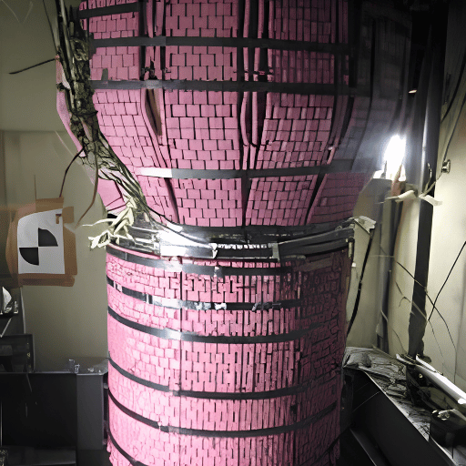
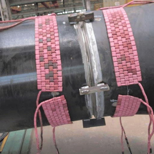
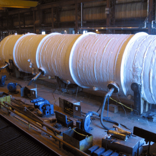
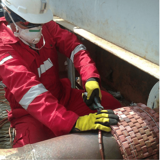
- Electrical resistance heating (ceramic-pad blankets): Flexible ceramic heating pads are arranged around the weld. In these pads, a resistance wire generates heat, which is transferred into the surface of the object to be welded. Thermocouples are welded to the part by capacitor-discharge method, the pads put on and topped with thermal insulating blankets.These are by far the most common on-site method applied on pipe work. Longer time constant, the use of PID control logic necessary for avoiding overshoot.
- A flexible coil is wrapped around the weld area and the alternating current within the coils creates a current within the metal that heats from within. Quick thermal response, lowest long term cost forconsumables, and reusable induction coils is making induction a favorite tool for high volume piping fabrication.
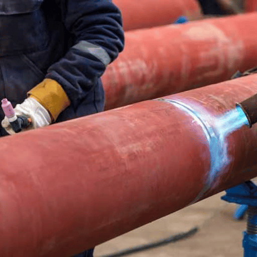
- high velocity gas burners for when larger areas of the material need to be treated, or when firing inside a pressure vessel is to be applied (use the vessel shell itself as a furnace) Poor degree of temperature control
Soak Band Requirements
241562 PWHT – For local PWHT, the width of the material in the soak band (which falls within a specified temperature range) cannot be less than code widths:
- ASME Section VIII: Soak band = 2 x weld thickness or 50.8mm (2”) of base material from the weld centre, whichever is smallest.
- ASME B31.3: Soak band = overall weld width + 1” (25.4mm) to both sides.
- BS EN 13445 heated band=5(Rt), R=vessel radius, t=wall thickness=5(vessel diameter divided by 2 X wall thickness)
Documentation Package
Un pack de documentation en 4 parties doit accompagner chaque cycle de PWHT pour une pièce conforme,
- Heat treat record (weld IDs, component, date, operator)
- Strip chart recorder trace (time-temperature curve for every thermocouple)
- Calibration certificate for thermocouples and recording equipment (NIST-traceable)
- Non Conformance Record (PWHT Procedure/any departure there off and resolution)
What Happens When You Skip PWHT?
Forgoing the post weld heat treatment (PWHT) when mandated—or when service conditions require it—gives rise to three classes of result: metallurgical problems that occur right away; failures during service that emerge after, not during, operation; and potentially costly questions of conformance and liability.
Immediate – Hardness & Microstructure: P91 welds in as-welded condition have HAZ hardness of 350-420HV (Code limit 250HB) making the weld area embrittled, and vulnerable to failure under impact or thermal shock prior to service.
Delayed-hydrogen cracking-Delayed hydrogen cracking can occur anytime between 24 and 72 hours after welding when welders and inspectors are long gone from the site. The hydrogen diffuses to hard haz microstructure sites where it creates the conditions for cracks to nucleate under a tensile residual stress and spread from locations with increased stress concentration.The failure of a number of offshore jack-up structure platforms has been traced directly to a failure to include a preheat or PWHT as part of the weld repairs.
In-service – Type IV cracking in P91: The predominant failure life limiting defect in power plant P91 welds is Type IV cracking which is initiated in the fine-grained HAZ where the weld and base material metals meet due to creep of the weldments in the residual stress zone of the HAZ. The appropriate application of PWHT with precise temperature control will significantly reduce this residual stress and delay crack initiation.
⚠ SCC Risk Without PWHT in Sour and Chloride Environments
Three elements are necessary for stress corrosion cracking to initiate and grow: material subject to embrittlement, the presence of a corrosive environment and an applied tensile stress. Proper post-weld heat treatment provides the third essential component. Tests have shown that one in-service weld that has undergone PWHT 650°C failed by IGSCC, yet in the as-weld state, this type of in-service weld has numerous cracking incidents.
Three elements are necessary for stress corrosion cracking to initiate and grow: material subject to embrittlement, the presence of a corrosive environment and an applied tensile stress. Proper post-weld heat treatment provides the third essential component. Tests have shown that one in-service weld that has undergone PWHT 650°C failed by IGSCC, yet in the as-weld state, this type of in-service weld has numerous cracking incidents.
PWHT in Power Generation: Boilers, Vessels, and Pipe Spools
No fabrication sector is subjected to more demanding service requirements as the power generation industry, due to factors such as; elevated pressures, thermal cycle loading, temperatures of several hundreds of degrees and decades of operational life time. Coupled with P91/P92 material requirements at all wall thicknesses, thick-section construction, and stringent in-service inspection schedules, it is clear why PWHT compliance defines project quality in power generation.
Prior weld quality determines how much work PWHT must do. A weld with poorly controlled inter-pass temperature deposits successive passes with elevated hydrogen content and hardened HAZ zones — heat treatment must compensate for these compounded problems. Robotic welding with integrated inter-pass temperature monitoring controls these variables upstream, delivering welds that respond more predictably to treatment.
📊 Case: Henan Province Boiler Header — Zhouxiang Robotic Welding System
To qualify 280 joints of tube-to-header welding at a coal fired power plant builder in Henan Province to comply with code 31.1 (max interpass temperature 250C P22 steel) our robotic welding solutions delivered consistent interpass temperature control on every joint via thermocouple and predictive software. Radiographic test reject rate reduction; (9.0%) manual vs. (1.8%) robot – an 80% decrease. 18-month pay back due to reduced remedial welding and PWHT testing cost.
To qualify 280 joints of tube-to-header welding at a coal fired power plant builder in Henan Province to comply with code 31.1 (max interpass temperature 250C P22 steel) our robotic welding solutions delivered consistent interpass temperature control on every joint via thermocouple and predictive software. Radiographic test reject rate reduction; (9.0%) manual vs. (1.8%) robot – an 80% decrease. 18-month pay back due to reduced remedial welding and PWHT testing cost.
📊 Case: Vietnam P22 Pipe Spool Production — ASME B31.1 Compliance
In Vietnam, a major EPC Contractor utilized a Zhouxiang automated pipe welding system for ASTM A335 P22 main steam line fabrication to ASME 31.1 code: includes; 200C preheat, automated interpass temperature control, PWHT, and 100% radiographic inspection producing14 spools per day. Robotic rejection rate (2.1%) vs. equivalent (as far as code requirement concerned), PWHT tracking included.
In Vietnam, a major EPC Contractor utilized a Zhouxiang automated pipe welding system for ASTM A335 P22 main steam line fabrication to ASME 31.1 code: includes; 200C preheat, automated interpass temperature control, PWHT, and 100% radiographic inspection producing14 spools per day. Robotic rejection rate (2.1%) vs. equivalent (as far as code requirement concerned), PWHT tracking included.
Controlling interpass temperature, i.e., above the code required minimum, and below any critical pre-set level is a key aspect of high quality Cr-Mo fabrication: maintaining it ensures that less hydrogen enters the weld during the welding process thereby reducing the potential for hydrogen related cracks prior to PWHT. It also greatly assists in shortening PWHT Soak Time and enables a more uniform weld microstructure for easier complete stress relaxation, thus minimizing rework. The benefit of integrating robotic welding into your process with precise automated control is undeniable from downstream PWHT results.
Learn how Zhouxiang supports power generation fabrication at Power Industry Welding Robot Solutions →
Post-PWHT Inspection: Hardness Testing and NDT
PWHT Completes the Loop. Confirming you get the desired metallurgical effects is the second part. This requires a programmed sequence of inspections to assess both the material (hardness for stress relief and temper) and the weld (NDT). The result will confirm PWHT hasn’t compromised weld integrity.
Hardness Acceptance Criteria
| Material / Grade | Max Hardness After PWHT | Test Method | Code / Reference |
|---|---|---|---|
| P91 — weld metal & HAZ | ≤ 250 HB / 265 HV / 25 HRC | Brinell or Vickers | ASME / many owner specs require 248 HB max |
| P-No. 1 carbon steel | ≤ 200 HB (industry standard); ≤ 225 HB (some specs) | Brinell | API 582; NACE for sour service |
| P-No. 1 carbon steel (typical range) | 140 – 160 HV in practice | Vickers | B31.3 does not mandate testing for P-1; API 582 does in corrosive service |
| Low-alloy Cr-Mo steels | ≤ 235 HV / ≤ 22 HRC | Vickers or Rockwell | NACE / ISO 15156 for sour environments |
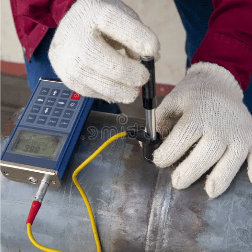
Hardness. ASME B31.1 and B31.3 specify hardness testing for 100% of local PWHT welds and at least 10% of batch-furnace treated welds when a hardness limit is mentioned. It is noteworthy that ASME B31.3, Table 331.1.1, does not specify a maximum hardness requirement for carbon steel, P-No.1-where local PWHT of carbon steel piping becomes a Code requirement through external specifications (client requirement or NACE).
NDT Sequence After PWHT
Non-Destructive Testing. It’s most common to conduct non-destructive testing of code-welded repairs following, not preceding, PWHT. This because PWHT may introduce certain residual stresses which could depress ultrasonic indications, and change in radiograph density, making detection of minor flaws harder.
- Radiography. The standard procedure for pipe butt welds in accordance with ASME B31.1 & B31.3 to assess post-PWHT volumetric indications like slag and porosity.
- Ultrasonic. More common for thick wall pressure vessels where geometry can affect radiograph film capture. (Time of Flight Diffraction, TOFD, is increasingly popular on P91 piping projects).
- Hardness traverse: Systematic hardness mapping across weld, HAZ, and base metal — typically 3–5 points per zone — validates PWHT effectiveness.
PWHT Trends and Outlook 2025–2026
3 Forces Are Pushing PWHT Beyond Its Current Limits.
GB/T 30583-2026-A New National Standard in China. The new Chinese GB/T 30583-2026 standard, “Specification for Post-Weld Heat Treatment of Pressure Equipment,” was issued in March 2026 by the State Administration for Market Regulation. For the first time, this standard presents an objective method beyond purelyempirical judgement. The Energy Difference Method, presented in Appendix G, relies on a physical principle linking residual stress levels to a calculable physical difference in work required to achieve certain indentations. When compared with an error margin of only 5MPa, contrasted with 15MPa when assessed by traditional methods such as X-ray diffraction, it represents a major advancement in evaluating PWHT results on carbon and low-alloy steel pressure equipment.
Increased demand for hydrogen infrastructure will boost utilization of specialized PWHT alloys. As development of hydrogen infrastructure-including electrolysis facilities, reformer technology and high-pressure distribution pipelines-accelerates, demand for P91 and P92 high-grade steels rises. Both alloys absolutely require pre and post-welding heat treatments, and have little or no tolerance for deviations from the specified temperatures, which means PWHT for these grades demands tightly controlled, ideally automated, quality assurance systems in fabrication.
Digital PWHT Monitoring: Strip chart recorders are being replaced by networked digital data loggers that have cloud-based documentation features. Remote viewing of live temperature data on dashboards allows remote QA personnel to see heat treat activity in progress, while thermocouple calibration certificates and heat treat records are now more commonly being embedded directly into the weld management software. Thermal Processing Magazine identified this digital shift — including predictive maintenance for PWHT equipment — as a defining 2024 trend. This aligns directly with ASME audit trail requirements, which mandate a clear chain of custody from thermocouple calibration through final cool-down sign-off.
Frequently Asked Questions About Post Weld Heat Treatment
Is post weld heat treatment required for all carbon steel welds?
No. ASME B31.3 (2014 and later) does not require PWHT on P-No. 1 materials at any thickness. But as soon as wall thickness exceeds 1” (25mm) on P-No. 1 you must preheat to a minimum 200F (95C). On ASME Section VIII P-No. 1 is only required at 1.25-1.50” wall thickness. Additionally, in sour services you may still require a PWHT per NACE/ISO 15156 based on hardness testing irrespective of material thickness.
What temperature is used for post weld heat treatment?
Hold time depends on material temperature requirements, and that in turn depends on material group. Carbon steel (P-No.1) is treated at between 1100-1325F (595-720C), typical Cr-Mo at between 1250-1350F (680-730C) and P91 at 1350-1425F (730-770C), with tight tolerance of ±30C across the weld and the surrounding zone. Too high a temperature and you approach Ac1 transformation, and risks re-austenitization followed by re-hardening as you cool. So “hotter is better” can be dangerously wrong. At over 790C (1450F), P91 starts to creep strength over time by permanently destroying fine dispersions of M23C6 precipitates. You’ll find the correct range required for any material on ASME Code Tables and weld procedure specifications.
How long does a PWHT cycle take?
A complete heat treat cycle involves controlled heating to the specified temperature, holding the workpiece at temperature (the soak), and a controlled cool-down below 400C (750F). For typical steel P-Nos, the soak alone is a minimum of 1-hour per inch of wall thickness, and P91 is a minimum 2-hours regardless of thickness. If I have a 2” thick vessel shell, my minimum soak alone would be two hours. This, together with time to heat the part evenly at the maximum ASME- allowed rates (e.g., 200F/hr for a 2” wall), then time to cool properly means the total cycle can be anywhere from 8-16 hours, depending on the piece and if on-site or shop treatment occurs.
Can PWHT be performed locally without putting the entire structure in a furnace?
Yes. Local PWHT is permitted under both B31.1 and B31.3 applications for pipe and nozzle welds, usually with electrical resistance heating blankets or induction heating coils. The ASME code specifications still require specific widths on either side of the weld, such that the soak band on each side is 2 X the weld thickness or 2” minimum, whichever is less on ASME VIII vessels; B31 codes generally use an 8” soak band for pipes. temperature coverage and uniformity are still the same as the furnace requirements and documentation is identical (strip chart, etc.).
What is the difference between preheating and post weld heat treatment?
Preheat and post weld heat treatment(PWHT) actually solve the same two problems-residual stress and hydrogen cracking-at two separate stages in the welding sequence. Preheat occurs before, during, and just after welding. Slowing down the rate at which the weld and HAZ cool allows diffusible hydrogen more time to diffuse out of the lattice and minimizes the thermal differential which induces residual stresses.
PWHT occurs after the complete weld has cooled. This relaxes residual stress, that has been locked into the weld, and, more importantly in the case of Cr-Mo grades, converts brittle martensite into a much tougher, tempered structure. More commonly, preheat is also required even when pwht is also performed.
Preheat without PWHT may satisfy some code exemptions; PWHT without preheat is rarely acceptable for high-alloy steels like P91.
Does stainless steel require PWHT after welding?
Conventional austenitic stainless steels (like 304 and 316) must NOT undergo thermal stress relief PWHT.The conventional temperatures used for carbon steel (595-720 C) place the part right in the window of carbide precipitation where corrosion is promoted; the process destroys the inherent corrosion resistance.Duplex steels often benefit from post-weld solution annealing(1020-1100 C)to reform their optimum microstructural balance but PWHT is distinct from this.
What hardness is acceptable after post weld heat treatment?
Acceptance criteria vary by material and application. P91 weld metal and HAZ must measure ≤250 HB (≤265 HV) after PWHT — many owner specifications tighten this to 248 HB maximum. Carbon steel P-No. 1 welds typically fall in the range 140–160 HV after PWHT; industry standard caps are 200 HB (API 582) and 225 HB for some non-sour applications. In sour H₂S environments, NACE/ISO 15156 limits weld metal and HAZ hardness to 22 HRC (approximately 237 HB) regardless of material, because higher hardness dramatically increases hydrogen sulfide stress cracking susceptibility.
Are Your Welds PWHT-Ready Before Treatment?
Robotic welding with automated inter-pass temperature control delivers consistent pre-PWHT weld quality — controlled HAZ microstructure, defined hydrogen content, and documented heat input on every joint. Zhouxiang has supported power generation fabricators from Henan to Vietnam with compliant welding systems for ASME B31.1 and ASME BPVC applications.