Get in Touch with Zhouxiang

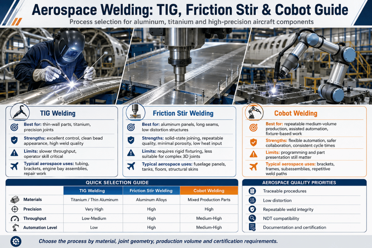
Aerospace welding sits at the demanding edge of metal joining. A single porosity-filled fillet on a turbine casing or a cracked friction stir seam on a cryogenic fuel tank can ground a fleet — or worse. This guide covers the processes (TIG, friction stir, electron beam, laser, plasma), the alloys (aluminum 2024/7075, Ti-6Al-4V, Inconel 718/625), the standards (AWS D17.1:2024, AS9100, Nadcap, ISO 24394), and the cobot and robotic systems that are now reshaping how fabrication shops compete for AS9100-certified contracts. Industry analysts project the global friction stir welding market to grow at a CAGR in the high single digits through 2033, and cobot welding searches are rising as fabricators look for a path to high-mix, high-skill work without losing welders to retirement.
Quick Specs — Aerospace Welding at a Glance
| Governing standards | AWS D17.1/D17.1M:2024 (fusion), AWS D17.2/D17.2M:2019 (resistance), AWS D17.3/D17.3M:2021 (friction stir of aluminum), AS9100, Nadcap AC7110, ISO 24394 |
| Core processes | GTAW (TIG), GMAW, friction stir welding (FSW), electron beam (EBW), laser beam (LBW), plasma arc (PAW) |
| Critical alloys | Aluminum 2024, 6061, 7075; Ti-6Al-4V; Inconel 625, 718; Waspaloy |
| Service envelope | −253°C liquid hydrogen tanks to >1,100°C jet engine hot-section |
| Inspection floor | 100% NDT (radiography, UT, PT, MT) on flight-critical welds; CT or PAUT for complex geometries |
| Supplier QMS | AS9100 quality system + Nadcap AC7110 welding accreditation expected by OEM primes |
What Is Aerospace Welding? (And Why It’s Different)
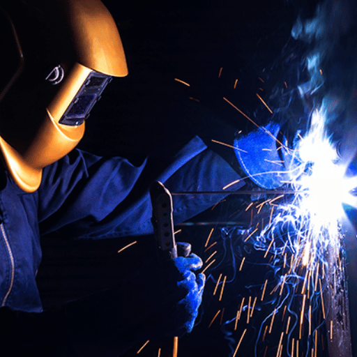
Aerospace welding is the practice of fusing or solid-state joining metals that have to survive the loading, vibration, thermal cycling, and corrosion environment of flight hardware. Components in scope are airframes, engines, exhaust systems, tubing for fuel and hydraulics, landing gear, pressure vessels, satellite buses, and rocket fuel tanks — anywhere a defect could propagate into a crack the airframe cannot tolerate. This is the formal scope adopted by the AWS D17 Committee on Welding in the Aircraft and Aerospace Industry.
What separates an aerospace weld from a structural-steel weld is not the equipment — it is the acceptance criteria, the documentation trail, and the inspection rigor. Three things shift:
- Defect tolerance shrinks toward zero. AWS D17.1 Class A welds reject pore clusters and undercut at thresholds that would pass for general fabrication.
- Cleanliness becomes a process input. Hydrated surface layers on titanium are a known mechanism for hydrogen-induced porosity, so prep, glove discipline, and shield-gas integrity matter as much as arc parameters (TWI).
- Every weld is traceable. Each part has a Welding Procedure Specification (WPS), a Procedure Qualification Record (PQR), a certified welder ID, and an NDT result — a paper trail kept under AS9100.
That is also why aerospace fabricators tend to specify weld processes by component rather than by shop habit. A repair shop will TIG-weld an aluminum exhaust collector ring at 100 amps; the same shop, working an integral fuel-tank stiffener, will spec friction stir welding because the joint sees pressurized cryogenic service and a fusion process would risk porosity that radiography cannot tolerate.
Aerospace Welding Processes — A Decision-Driven Comparison
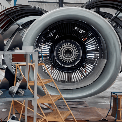
Five fusion processes and one solid-state process cover the bulk of aerospace work. Choosing among them is rarely an aesthetic preference; it is driven by the alloy, the section thickness, the joint geometry, and whether the weld sits in primary structure, secondary structure, or a repair situation.
TIG (Gas Tungsten Arc Welding, GTAW)
TIG is the default for thin-section aerospace work — exhaust collector tubes, hydraulic lines, sheet-metal skin repairs, and engine mount weldments. It tolerates fine control over heat input, runs clean enough for thin Ti-6Al-4V and Inconel sections, and accepts manual, mechanized, or orbital configurations. Hand TIG is still the dominant approach for MRO and short-run shops; orbital TIG dominates fuel and hydraulic tubing because it produces repeatable circumferential welds without rotating the part.
Why Is TIG Still the Default for Aircraft Tube and Exhaust Work?
Because the section thicknesses are small, the alloys (321 stainless, Inconel 625, Hastelloy variants) are sensitive to heat input, and the production volumes per part number rarely justify capital equipment for friction stir or electron beam. TIG gives a welder direct control over puddle and filler addition, which matters when the wall is 0.040″ (~1 mm) and a 50° flame angle deviation can blow through. As one r/Welding contributor put it after years on TIG, holding the torch closer to vertical gives the trailing argon shroud a chance to actually protect the cooling weld — a small detail that field welders learn before any textbook covers it.
Friction Stir Welding (FSW)
FSW was invented at The Welding Institute (TWI) in 1991 and adopted by aerospace specifically to join aluminum sections that fusion processes struggle with. A rotating non-consumable tool plunges into the seam, the friction-generated heat plasticizes the metal below its melting point, and forging pressure consolidates the joint. Because the metal never liquefies, FSW avoids solidification cracking and porosity entirely — which is exactly why NASA chose it for the Space Launch System (SLS) Core Stage cryogenic tanks. NASA went further and developed Friction Pull Plug Welding to close out the self-reacting friction stir welds on SLS fuel tank dome-to-barrel joints, a technique that does not exist in any commercial weld shop because it was engineered for one mission profile.
When Should You Use Friction Stir Welding Instead of TIG?
Use FSW when the joint is aluminum, the section is at least 3 mm thick, the geometry is linear or circumferential, and the volume justifies the capital cost. Typical FSW applications are 2024 and 7075 panel seams for fuselage skins, 2219 dome welds on fuel tanks, and stringer-to-skin joints on launch vehicles. Use TIG instead when the section is thin (<2 mm), the alloy is not aluminum, the joint geometry is non-linear (saddles, complex tubing intersections), or the production volume is <100 parts. Published AWS D17.3/D17.3M:2021 covers FSW of aluminum for aerospace specifically; thermal or stainless FSW falls outside its scope.
Electron Beam Welding (EBW)
EBW is the workhorse of jet engine manufacturing. In a vacuum chamber, a focused electron beam drives a narrow keyhole down through 25 mm or more in a single pass, with a heat-affected zone an order of magnitude narrower than arc welding. Turbine discs, compressor drums, and afterburner segments are routinely EBW’d in nickel superalloys including Inconel 718 and Waspaloy. Vacuum environment eliminates atmospheric contamination, which matters when the next step in the production sequence is hot isostatic pressing and any porosity would propagate.
Laser Beam Welding (LBW)
Laser welding gives a similarly narrow heat-affected zone without the vacuum overhead. Fiber and disc lasers in the 4-8 kW range weld aircraft skin panels, hermetic enclosures for avionics, and increasingly the stringer-to-skin joints on twin-aisle airframes. Modern LBW cells couple a robotic arm to a scanner and run in inert-shroud or local-vacuum modes. Throughput on a metric skin panel runs roughly an order of magnitude higher than mechanized GTAW.
Plasma Arc Welding (PAW)
PAW sits between TIG and EBW in capability. Its constricted plasma column gives keyhole-mode penetration on sections up to about 10 mm with a heat input lower than conventional TIG, making it useful for high-temperature alloy welds where distortion control matters. Combustion liners, fuel injector bodies, and certain titanium component joints are still routinely PAW’d.
Process Comparison Table
| Process | Typical alloys | Section range | Strength | Where it shows up in aircraft |
|---|---|---|---|---|
| TIG (GTAW) | Al, Ti, Ni, stainless | 0.5 – 6 mm | Manual control, broad alloy range | Exhausts, hydraulic tubing, engine mounts, MRO repair |
| FSW | Al 2024 / 2219 / 6061 / 7075 | 3 – 25 mm | No porosity, no solidification cracking | Fuel tanks, fuselage skin seams, launch vehicle stringers |
| EBW | Ni superalloys, Ti, refractory | 2 – 50 mm single pass | Narrow HAZ, vacuum-clean | Turbine discs, compressor drums, afterburner segments |
| LBW | Al, Ti, stainless, Ni | 0.5 – 12 mm | Speed, low distortion | Skin panels, avionics enclosures, T-stringer-to-skin |
| PAW | Ti, Ni alloys, stainless | 1 – 10 mm | Keyhole at lower heat input | Combustion liners, fuel injector bodies |
📐 The 4-Tier Aerospace Welding Decision Matrix
Cross-reference the criticality tier with the material to land on a defensible process choice before specifying equipment:
- Tier 1 — Flight-critical (pressure vessels, primary load path): Ti-6Al-4V → orbital TIG or EBW · Inconel 718 → EBW · Aluminum 2219 → FSW. AWS D17.1 Class A acceptance, Nadcap AC7110 supplier.
- Tier 2 — Primary structure (fuselage skin, stringers, ribs): Aluminum 2024/7075 → FSW (linear), LBW (curved skin) · titanium plate → PAW or EBW. AWS D17.1 Class A.
- Tier 3 — Secondary structure (brackets, ducting, exhaust collectors): Aluminum 6061 → TIG · stainless and Inconel → TIG · sheet-metal joints → resistance spot per AWS D17.2. AWS D17.1 Class B is often acceptable.
- Tier 4 — MRO and repair welding: TIG dominates because field repair is geometry-irregular, low-volume, and requires welder judgement. Repair WPS qualified to the OEM repair manual takes precedence over D17.1 directly.
Engineering Note — Heat Input Targets per Process
📐 Engineering Note
As a starting point: TIG on 2 mm Ti-6Al-4V runs 80-120 A DCEN with 100% Ar primary + trailing shield (15-25 CFH primary, 10-15 CFH trailing). FSW on 6 mm 2024 runs 600-800 rpm with a traverse rate of 100-200 mm/min and a forge force of 8-15 kN, but the window is alloy- and tool-geometry-specific. EBW on 25 mm Inconel 718 uses 60-150 kV at 50-200 mA with a focal spot ≤0.5 mm. These are starting parameters — every WPS still has to be qualified by PQR per AWS D17.1.
Material-Specific Challenges — Aluminum, Titanium, and Inconel
Three alloy families dominate aerospace welds for primary aircraft structures, and each fails in a characteristic way. Knowing the failure mode up front is what separates a WPS that survives qualification from one that gets sent back from the inspector.
Aluminum Alloys (2024, 6061, 7075, 2219)
Aerospace aluminum is split roughly between heat-treatable (2xxx, 6xxx, 7xxx) and non-heat-treatable (3xxx, 5xxx) families. Heat-treatable alloys are also the difficult ones to fuse-weld: 2024 and 7075 are practically un-weldable by fusion because the heat input destroys the precipitation-strengthened temper and hot-cracks during solidification. That is why every long aluminum aerospace seam now built — Boeing 787 floor beams, Airbus A380 fuselage panels, NASA SLS hydrogen tank dome — uses FSW rather than fusion welding.
2219 (an aluminum-copper alloy) and 6061 are different. 2219 is FSW-friendly and fusion-weldable, which is why launch vehicle tanks have used it since Saturn V. 6061 fusion-welds readily but loses about 25-30% of its T6 tensile strength in the HAZ, so post-weld heat treatment (T6 re-aging) is normally specified for primary structure.
Titanium (Ti-6Al-4V, CP Grade 2/3)
Titanium’s weld defect of record is porosity, and the mechanism is hydrogen dissolution. TWI documents that hydrated layers on the joint surface — moisture, hydrocarbons, cutting fluid residue — release hydrogen into the molten pool during welding, where its solubility in liquid titanium far exceeds its solubility in solid. Trapped hydrogen comes back out of solution during cooling and forms the pores that ground a part. Mitigation is procedural, not metallurgical: degrease with non-halogenated solvent, mechanically clean within hours of welding, store cleaned coupons in dry cabinets, and run trailing argon long enough that the back side of the weld stays below 425°C in air.
Beyond porosity, titanium also exhibits contamination embrittlement. Above about 480°C in air, titanium picks up oxygen, nitrogen, and hydrogen interstitially. A visible signal is a colour change from silver to straw to blue to grey to white — and white is reject. A documented failure case on AMS 4975 titanium air bottles traced excessive porosity directly back to a welding-technique deficiency in shield gas coverage. Shield gas integrity is non-negotiable.
Nickel Superalloys (Inconel 718, Waspaloy, Inconel 625)
The nickel-iron and nickel-base alloys used in jet engines fail at the weld in two ways: strain-age cracking during post-weld heat treatment and microfissuring in the HAZ during welding. Mitigation strategies are alloy-specific. Inconel 718 is the most widely used because its age-hardening reaction is sluggish enough that strain-age cracking is manageable with controlled heat input and a stress-relief cycle. Waspaloy is harder to weld for the opposite reason — its faster age-hardening response means more careful pre-heat and post-weld thermal management. Filler metals matter: Inconel 625 base is often welded with ERNiCrMo-3 filler; Inconel 718 typically uses ERNiFeCr-2 (Inconel 718 matching filler).
📐 Engineering Note — Shielding Discipline for Ti-6Al-4V
Primary cup argon flow: 15-25 CFH (cup ID 9-12 mm). Trailing shield: 10-15 CFH over the cooling pool with the trail length sized so that the metal exits the shield below 425°C. Back-purge for tubing welds: 5-10 CFH with O₂ meter on the exhaust reading <100 ppm before strike. Cleanliness: lint-free wipe with isopropyl or methyl ethyl ketone within 4 hours of strike; no fingerprints on the weld zone.
Standards and Certifications — AWS D17.1, AS9100, Nadcap, ISO 24394

A working aerospace welding program rests on three layers: a process specification (AWS D17.x), a quality management system (AS9100 or its Aerospace Industries Association equivalent), and a special-process accreditation (Nadcap AC7110). An international option is ISO 24394. Reading a Mill Test Certificate or a supplier audit report is mostly an exercise in confirming the right combinations.
AWS D17.1/D17.1M:2024 — Fusion Welding for Aerospace
D17.1 is the umbrella specification covering fusion welding of aluminum, steel, stainless, titanium, and nickel alloys for aerospace applications. Its 2024 edition is the fourth revision, and the committee summary published via ANSI documents that several fundamental changes were made to expand the document’s use and applicability. It governs procedure qualification (PQR), welder performance qualification, inspection acceptance criteria, and documentation requirements. Two classes exist: Class A for the most safety-critical welds (engine and pressure vessel work) and Class B for secondary structure.
What’s the Difference Between AWS D17.1, D17.2, and D17.3?
D17.1 governs fusion welding (TIG, GMAW, plasma, electron beam, laser). D17.2/D17.2M:2019 covers resistance welding — primarily spot and seam welding for aluminum and steel sheet-metal aerospace structures. D17.3/D17.3M:2021 is the friction stir welding standard, and it is scoped specifically to aluminum alloys for aerospace, because that is where FSW has been industrially validated. If a supplier portfolio claims aerospace welding capability but holds only D17.1, they probably cannot do resistance spot welding on aluminum nor friction stir on tank domes. Published documents are listed on the D17 Committee page.
AS9100 — The Quality Management System
AS9100 is the aerospace adaptation of ISO 9001, published by SAE International and adopted by the International Aerospace Quality Group (IAQG). It is the quality system that governs how a fabrication shop runs — document control, configuration management, training records, calibration, supplier control, internal audit. It is not a welding standard per se, but every major prime contractor (Boeing, Airbus, Lockheed Martin, GE Aerospace, Raytheon) requires AS9100 as a baseline.
Nadcap AC7110 — Special Process Accreditation for Welding
Nadcap (National Aerospace and Defense Contractors Accreditation Program) is an industry-managed approval system administered by PRI. AC7110/x audit checklists are specific to welding sub-disciplines: AC7110/12 covers electron beam, AC7110/5 covers torch and induction brazing, and AC7110 itself covers fusion welding. A supplier without Nadcap can still sell into aerospace, but most flight-hardware purchase orders from primes require it.
ISO 24394 — The International Alternative
For programs operating outside the U.S. or in mixed European/Asian supply chains, ISO 24394 covers aerospace welding requirements at a level similar in scope to D17.1. Both standards do not have identical acceptance criteria, but they cross-reference each other on procedure qualification and welder testing. Programs running FAA or EASA airworthiness oversight often default to ISO 24394 when the supply chain crosses the Atlantic, because European primes are familiar with it. Equipment-level differences also creep in across geographies — North American shops are heavier on Miller Electric and Lincoln Electric power supplies, while European primes more often spec EWM or Fronius for their qualified WPS — but all of those equipment lines can be procedure-qualified to either standard.
Inspection and Non-Destructive Testing — Verifying Aerospace Weld Quality
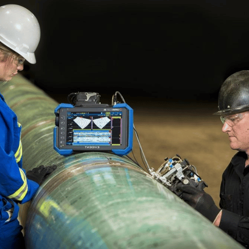
For flight-critical welds the inspection floor is 100% NDT — every weld is examined by at least one method, often two, before the part can be released. Inspection methods are not interchangeable; each catches a specific defect class.
| NDT Method | Detects | Min defect size | Where it is mandatory |
|---|---|---|---|
| Radiography (RT) / digital X-ray | Volumetric defects — porosity, inclusions, lack of fusion, lack of penetration | ~2% of section thickness | All Class A fusion welds; pressure vessels; tanks |
| Ultrasonic (UT) / PAUT | Planar defects — cracks, lack of fusion, laminations | 0.5-1.0 mm with PAUT | FSW seams; thick-section EBW; complex geometries |
| Dye Penetrant (PT) | Surface-breaking cracks, porosity, undercut | ~0.025 mm surface opening | Non-magnetic surfaces — Al, Ti, austenitic stainless, Ni alloys |
| Magnetic Particle (MT) | Surface and near-surface cracks | ~0.025 mm surface, ~1 mm subsurface | Ferromagnetic steels — landing gear forgings, fasteners |
| Computed Tomography (CT) | 3D volumetric — internal porosity, voids, geometry | ~50 μm voxel for small parts | Additively manufactured components; complex castings |
A typical Class A fusion weld inspection workflow runs: visual examination per WPS, dye-penetrant on surface, radiography for volumetric defects, and for sealed pressure boundaries a hydrostatic or helium leak test. UT is added on FSW and thick-section EBW because radiography is poor at finding planar lack-of-fusion in long aluminum seams.
- ✔Verify WPS and PQR are current and signed by the cognizant Engineering Authority
- ✔Confirm welder qualification record covers position, alloy, and thickness range
- ✔Inspect filler metal lot number, heat number, and storage condition
- ✔Verify shield-gas certificate (5N argon for titanium, 4N for general use)
- ✔Confirm pre-weld cleanliness — visual + UV-fluorescent check on Ti
- ✔NDT to AWS D17.1 acceptance with Level II/III inspector sign-off
Robotic and Cobot Welding in Aerospace — Where Automation Wins
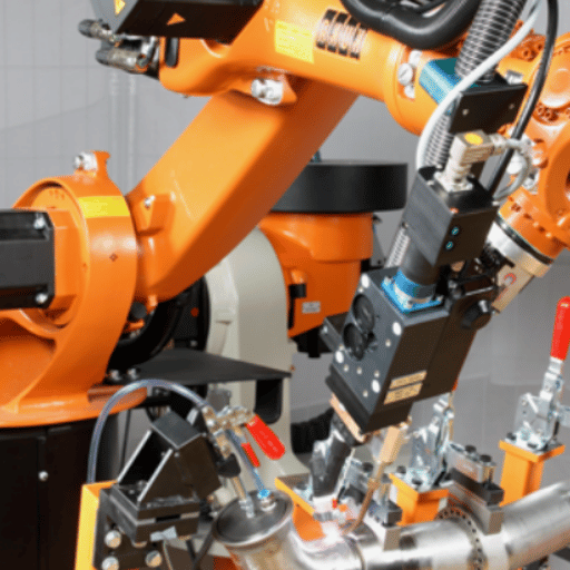
Aerospace was historically slow to adopt robotic welding for the same reasons it remains slow to adopt automation in general — low part-number volume, complex geometries, cleanroom constraints, and a regulatory environment that prizes deterministic process control. That picture is changing. Friction stir welding of launch vehicle tank domes is now done routinely by gantry-mounted robotic FSW systems. Airbus runs automated welding cells for structural components. SpaceX welds Starship stainless steel sections with custom-developed automated rigs. And on the smaller end, fabrication shops supplying secondary structure to primes are introducing collaborative welding robots to address welder shortages while preserving the AS9100 traceability the prime requires.
Can Cobot Welding Actually Meet Aerospace Quality Requirements?
Yes — within a specific application envelope. A cobot welding system meeting AWS D17.1 needs three things that an industrial robot also needs: closed-loop arc parameter control with logged WPS compliance, repeatable joint approach within ±0.2 mm, and a fume-and-radiation envelope that satisfies the cleanroom. An advantage of the cobot form factor is that the cell can be installed and reprogrammed in days rather than weeks, which matters in a high-mix shop where each work order may run 20-150 identical parts. Speed is the compromise — most cobot welders run at lower travel speeds than an industrial six-axis cell with positioner — so the volume threshold above which a full industrial cell wins out is somewhere around 200-500 parts per month for typical bracket and ducting work. Where cobots presently struggle in aerospace: very large geometries, vacuum-environment welds (EBW), and processes where the operator-cobot proximity rules limit production speed.
Three Real Deployments
NASA SLS Core Stage — Friction stir welding of the Core Stage liquid hydrogen and liquid oxygen tanks is automated at the Michoud Assembly Facility using a Plug Weld Tool developed for the program. Both vertical and circumferential FSW seams run on gantry-mounted systems, with weld parameters logged for every linear millimetre.
Universal Robots/Raymath — A documented IFR case study describes Raymath, an Ohio fabricator, automating complex TIG welding alongside MIG welding using Universal Robots cobots, with reported productivity gains of 200% on welding tasks and 600% on machine tending. This deployment pattern — high-mix secondary structure, modest volume, AWS-codified welds — generalizes to many aerospace-tier suppliers.
FSW in commercial aviation — Eclipse Aviation pioneered FSW for fuselage skin joining on the Eclipse 500 in the early 2000s. Commercial Crew vehicles and several twin-aisle airframes now use robotic FSW for aluminum panel seams, with the long, linear geometry being a near-ideal match for robotic FSW heads.
When Not to Automate
MRO and repair welding remains overwhelmingly manual, and that is the right answer. A typical engine cowl repair sees damage geometry the WPS could not anticipate, fitup that depends on shimming and tack judgement, and a part-number volume of one. Cobot or robotic deployment in that context would force-fit the wrong tool to the job. Same logic applies to early-stage prototype welding, where the geometry is changing each build, and to highly complex spatially curved tubing intersections that a six-axis arm cannot reach without major fixturing investment.
Common Failure Modes and Defect Prevention
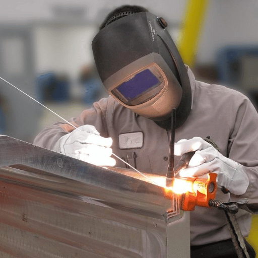
Most aerospace weld rejects fall into a small number of repeat-offender categories. Knowing them up front is the difference between a first-time-yield Class A weld and a part that goes through the inspection loop twice.
| Defect | Root cause | Prevention | Detection |
|---|---|---|---|
| Porosity (Ti, Al) | Hydrogen from hydrated surfaces; inadequate shield gas | Mechanical cleaning <4 h pre-weld; verified gas purity; trailing shield | RT, CT |
| Lack of fusion | Insufficient heat input; poor joint preparation | PQR-qualified parameter window; preheat per WPS | UT/PAUT, RT |
| Strain-age cracking (Ni superalloy) | Stress concentration + ageing during PWHT | Controlled cooling; intermediate stress-relief; revised PWHT cycle | PT post-PWHT, UT |
| Contamination embrittlement (Ti) | Air exposure >480°C; loss of trailing shield | Verified trailing-shield length; weld colour acceptance per WPS | Visual (colour), bend test on coupons |
| Distortion / residual stress | Excessive heat input; uneven welding sequence | Sequence planning; fixturing; PWHT for thick sections | Dimensional inspection, RS measurement |
| Hot cracking (Al 2024/7075 fusion) | Crack-sensitive alloy in fusion welding | Switch to FSW; if fusion required, use 4043 filler with 2xxx | RT, PT |
⚠️ Field-Reported Recurring Errors
Three repeat-offenders show up across welder forums and AWS technical discussions: trailing-shield breaks during titanium tube welds (welder repositions and the cooling weld loses cover); insufficient pre-clean before TIG on stainless lap joints that creates apparent porosity in dye-penetrant inspection; and over-aggressive heat input on 6061-T6 brackets that drops HAZ strength below substitution alternatives. Fix in each case is procedural, not technical — slow down, verify, and treat the WPS as the floor not the ceiling.
Industry Outlook — FSW Market, Cobot Adoption, and Sustainability (2026 and Beyond)
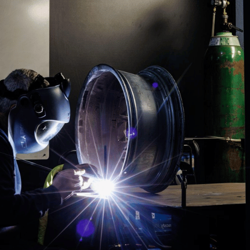
Three signals are shaping aerospace welding through the late 2020s. Independently they are interesting; together they suggest where to direct capital and training over the next three to five years.
FSW market expansion. Several independent market analyst groups place the global friction stir welding market in the $250-300M range for 2026, with projections forward through 2033 clustered at CAGR figures in the high single digits. Aerospace share is anchored by NASA, Boeing, Lockheed Martin, and the new commercial space programmes; growth pulled higher by FSW adoption in EV battery enclosures and rail rolling-stock fabrication outside aerospace.
Cobot adoption is accelerating. DataForSEO search-volume signals on “cobot welding” and “welding cobot” are rising year-on-year, and equipment vendors are adapting product lines specifically to the high-mix, low-volume aerospace supplier segment. Behind this sits a structural shortage of certified welders — Bureau of Labor Statistics projections suggest the U.S. welder labour pool needs roughly 80,000-90,000 new entrants per year just to backfill retirements, and aerospace-certified welders are a smaller subset of that. Cobot welding does not solve the problem alone, but it amplifies the productivity of each remaining certified welder, which is the practical mitigation.
Standards modernization. AWS D17.1’s fourth edition released in 2024 includes provisions that broaden the document’s applicability — a quiet but important update for shops that have been working from the older edition. The published D17.3:2021 already covers FSW of aluminum, and committee work on additive-manufacturing post-processing welding is advancing. ISO and EASA updates run on slightly different cycles, but the direction is the same: more processes, more alloy combinations, tighter documentation.
If You’re Specifying a 2026-2027 Fabrication Cell
- For batch jobs of 50-500 parts per month on secondary structure, evaluate a cobot welding system as the default — not a manual cell.
- Specify the AWS D17.1:2024 edition explicitly in supplier purchase orders, not “current edition.”
- For aluminum primary structure with linear seams >3 mm thick, evaluate FSW capability before specifying fusion welding.
- Confirm that NDT capability scales with throughput — automated welding cells produce data faster than manual radiography review.
Frequently Asked Questions
Q: What welding processes are approved for aerospace applications?
View Answer
Fusion welding processes approved under AWS D17.1 include gas tungsten arc (TIG/GTAW), gas metal arc (MIG/GMAW), plasma arc, electron beam, and laser beam. Resistance welding is covered by AWS D17.2. Friction stir welding of aluminum alloys is covered by AWS D17.3.
Q: When should you use friction stir welding vs TIG welding for aircraft?
View Answer
Use FSW when the joint is aluminum (2024/2219/6061/7075), the section is 3-25 mm, and the geometry is linear or circumferential — fuselage skin seams, tank dome welds, stringer joints. FSW eliminates porosity and solidification cracking, which makes it the default for cryogenic pressure boundaries. Use TIG when the section is thinner than about 2 mm, the alloy is titanium or a nickel superalloy, the geometry is non-linear (saddles, complex tube intersections), or the production volume is low enough that FSW tooling capital cannot be justified. TIG remains the default for exhaust systems, hydraulic tubing, and MRO repair.
Q: Is Nadcap certification required for all aerospace welding suppliers?
View Answer
Not legally required, but commercially mandatory for most flight-hardware purchase orders from major primes (Boeing, Airbus, Lockheed Martin, GE Aerospace, Raytheon). A supplier without Nadcap AC7110 can still produce welds, but most prime contractors will route the work to an accredited supplier instead.
Q: Can cobot welding meet AWS D17.1 requirements?
View Answer
A cobot welding cell can be qualified to AWS D17.1 the same way an industrial robotic cell is — through procedure qualification (PQR), welder performance qualification, closed-loop parameter logging, and dimensional repeatability evidence. Cobot hardware itself is not the gating factor; the questions are whether the cell can hold joint approach within ±0.2 mm, whether arc parameters are recorded for every part, and whether NDT can confirm acceptance at the throughput required. Within secondary structure and batch jobs of 50-500 parts per month, the answer is increasingly yes. Above 500 parts per month a full industrial cell typically wins on cost-per-weld. Vacuum-chamber processes (EBW) and very large geometries remain outside the cobot envelope today.
Q: How does aerospace welding inspection differ from general welding QC?
View Answer
General welding QC may rely on visual examination, with sampling NDT on a subset of welds. Aerospace welding on flight-critical hardware typically requires 100% NDT — every weld inspected — using radiography, ultrasonic, dye penetrant, and magnetic particle as appropriate to the alloy and geometry. The acceptance criteria are stricter (smaller allowable defect sizes), and the entire workflow — WPS, PQR, welder ID, NDT result — is retained for the life of the airframe.
About This Analysis
This guide synthesizes published AWS D17 Committee documents, NASA Marshall Space Flight Center technical disclosures on friction stir welding for the Space Launch System, TWI research notes on titanium porosity, and the IFR case study record on cobot welding deployments. Where market figures are cited, they are presented as published ranges from independent analyst groups rather than as single-source data points. Process parameter starting values are illustrative; every Welding Procedure Specification must be qualified to AWS D17.1 by procedure qualification record before production use. Reviewed by the zxweldingrobot engineering team.
References & Sources
- AWS D17 Committee on Welding in the Aircraft and Aerospace Industry — American Welding Society
- AWS D17.1/D17.1M:2024 Specification for Fusion Welding for Aerospace Applications — American Welding Society
- AWS D17.3/D17.3M:2021 Specification for Friction Stir Welding of Aluminum Alloys for Aerospace Applications — American Welding Society
- AWS D17.1:2024 Fourth Edition — Summary of Changes — American National Standards Institute
- Space Launch System Core Stage Plug Weld Tool — NASA
- Advanced Metal Joining Facility — Friction Pull Plug Welding — NASA Marshall Space Flight Center
- Causes of Porosity in Titanium Welds — Technical FAQ — The Welding Institute (TWI)
- Case Study on Excessive Porosity in AMS 4975 Titanium Air Bottle Welds — Loyola Marymount University
- Cobots Boost Production 200% on Welding (Raymath Case Study) — International Federation of Robotics