Get in Touch with Zhouxiang
Quick Specs: Cantilever Welding Robot for Shipbuilding
- A×is Configurations: 7-axis (6+rail), 8-axis (6+rail+Y), 9-axis (6+rail+Y+positioner)
- Ground Rail Length:6 m to 30+ m(Custom lengths)
- Welding Accuracy: ±0.1 mm with laser seam tracking (manufacturer-rated)
- Supported Processes: MIG/MAG, arc welding, TIG, hybrid laser-arc
- 7-axis – 3D robot model teach-in or non-teach via import (Tekla, SOLIDWORKS, UG) or point cloud reverse design
- Application: Hull panels, bulkheads, deck parts, structural framework, H-beams
Shipbuilders worldwide are facing a perfect storm of accelerating demand and a shrinking skilled labor force. The IFR World Robotics 2025 Report registered 542,000 installations of industrial robots in 2024 alone- twice as many as a decade ago. In shipbuilding, where hull panels are 10+ meters long and weld seams extend in the hundreds of linear meters per vessel, the cantilever welding robot has become the standard configuration to address the requirement of automating large-scale welding tasks.
This report outlines the engineering principles behind cantilever welding robots, provides a comparison of 7 axis, 8 axis and 9 axis configurations, and discusses what shipyard managers and welding engineers should expect in terms of specifications, setup parameters, and return on investment. All claims are supported by traceable data- and where data is limited, acknowledged.
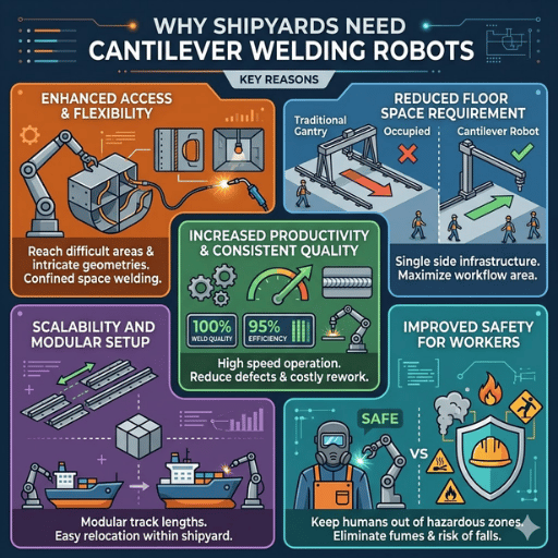
Why Shipyards Need Cantilever Welding Robots
Shipbuilding’s welding workforce is aging at precisely the wrong time. According to the American Welding Society, projections show that by 2028 the United States alone will require over 330,000 new welding professionals- roughly 82,500 per year. Average age of a welder today is 55, and for every five retiring welders two new ones enter the trade.
Shipbuilding feels the impact of this trend more than other industries. Commercial and naval yards face competition from construction, energy and automotive companies for the same shrinking workforce; delays to production from lack of personnel are not hypothetical but verified constraints to active Navy procurement programs.
330,000+
Welding professionals needed by 2028 (AWS)
542,000
Industrial robots installed globally in 2024 (IFR)
55 years
Average age of active welders in the U.S.
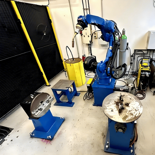
Cantilever welding robots solve the specific problem facing shipbuilders who are operating with fixed robotic cells- the workpiece is too large to be moved to the robot, and so the robot must be moved to the workpiece. A cantilever frame suspended from a ground rail advances along hull sections and panel assemblies, allowing the robot to reach into deep structures that otherwise would be outside the reach of a stationary arm. This mobility-centric approach sets cantilever systems apart from the more typical fixed-articulated robotic units attached to factory floors.
Shipyard practitioners collectively agree that welding automation in the shipbuilding industry is not about replacing human welders, but about multiplying the productivity of the diminutive number of welders in the shipyard- one generalist trading the discrete dockside panel over the seam for multiple panels assisted by parallel robot operators.
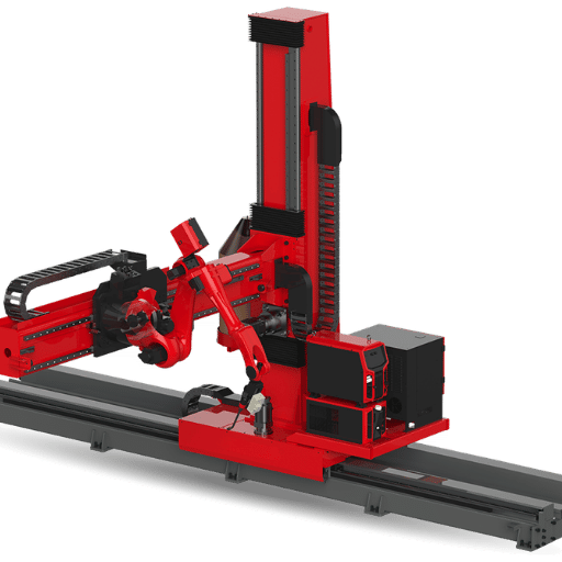
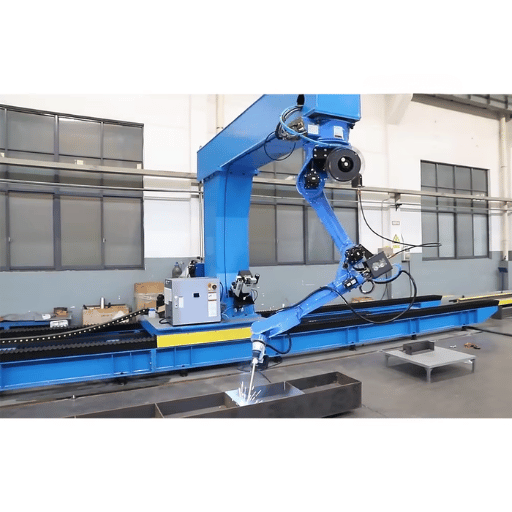
How a Cantilever Welding Robot Works: Architecture and Motion System
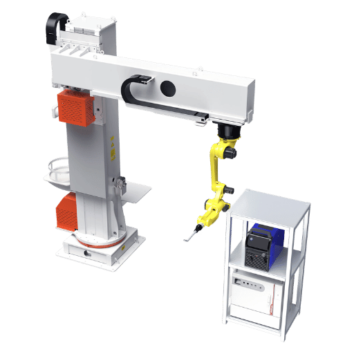
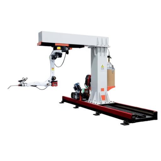
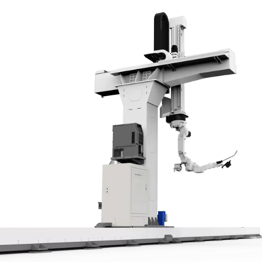
A cantilever welding robot is comprised of a 6-axis standard articulated arm, positioned atop an elevated cantilever structure that travels on a ground rail assembly. Its cantilever structure extends the work envelope in both the Y-axis and Z-axis without the need to manipulate the workpiece.
Core Components
Multiple subsystems of the cantilever welding work station feed into:
- Ground rail (X axis)- steel track assembly up to 30+ meters in length, conveying the entire cantilever assembly. Travel speed in the range of 8 meters/minute.
- Cantilever beam (Y / Z axis)- elevated arm assembly positioning the robot above and into the workpiece. Typical travel efficiency in the Y axis around 2 meters.
- 6 axes robotic arm- standard industrial arc welding robot (Fanuc, ABB, KUKA, or Yaskawa are popular decision) mounted at the end of the cantilever.
- Welding power source- digital inverter with pulse capability, designed for matching to the welding process (MIG/MAG, TIG, or hybrid).
- 3D vision and laser seam tracking- wide angle camera for workpiece scanning plus laser sensor for real time correction of seam deviation.
- PLC control system- manages motion on all axes, controls welding parameters, and manages integration and interface with the teaching free programming system.
A defining distinction between cantilever and gantry configurations is single-sided support- with cantilever beam stretch, the longer the cantilever the greater the potential deflection at the end of the Tool. While many modern systems compensate by laser seam tracking (which dynamically adjusts the welding weld path) fabricators working with tight tolerance weld seams should consider this design feature when specifying systems.
Engineering Note: Cantilever beam deflection (about the Y-axis) is proportional to the cubed length of the cantilever. At approximate rated payload use 0.05 0.15 mm static deflection at the Tool tip (before seam tracking correction). Laser seam tracking system corrects geometrical errors dynamically, but the servo speed of the laser tracking sensor (50 100 Hz typical) often becomes the bottleneck in welding speed with complex curved welds. When buy of cantilever systems specify servo speed of the laser tracking not just the rated accuracy.
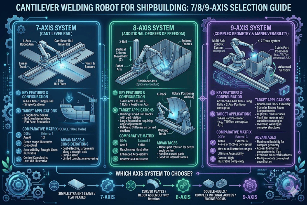
7-Axis vs. 8-Axis vs. 9-Axis: Which Configuration Fits Your Shipyard?
Number of axes on a cantilever welding robot is the sum of (a) the 6 axes of the robotic arm and (b) the external axes added by the cantilever, rail and positioner system. Each added axis increases the systems marginal capabilities- enabling work on greater spatial complexities and broader capabilities- but also marginally raising costs and space needs.
| Specification | 7-Axis | 8-Axis | 9-Axis |
|---|---|---|---|
| External Axes | 6 robot + 1 ground rail (X) | 6 robot + ground rail (X) + Y-axis | 6 robot + ground rail (X) + Y-axis + positioner rotation |
| Working Envelope | Custom length × 3.0 m × 0.5 m | Custom length × 3.5 m × 0.5 m | Custom length × 3.5 m × 0.5 m + rotation |
| Welding Positions | Flat (1G), Horizontal (2G) | Flat (1G), Horizontal (2G) | All positions: 1G, 2G, 3G (vertical), 4G (overhead) |
| Ground Rail Length | 6–30+ m | 6–30+ m | 6–30+ m |
| Welding Processes | MIG/MAG, Arc | MIG/MAG, Arc | MIG/MAG, Arc, TIG, Hybrid |
| Best Shipyard Use Case | Flat panel assembly, H-beam fillet welds | Panel sections with stiffeners, wider structural components | Complex hull frames, multi-position bulkhead welding, curved structures |
| Load Capacity (typical) | Up to 2,000 kg | Up to 2,000 kg | Up to 2,000 kg + positioner capacity |
Selection guidance by shipyard type:
- Small to mid panel shops welding flat panels and H-beam stiffeners: 7 axes-axes configuration performs 1G and 2G type welds most economically.
- Mid size yards welding wider structural components and partition plates will benefit from 8 axes configuration- with a Y-column that allows the robot to reach deep into asymmetrical and wide assemblies without repositioning the workpiece- saving crane hours.
- Large shipyards working on the hull frame, complex bulkheads, and curved forms will benefit from 9 axes- with positioner and all-position welding (including the overhead and vertical welds) capable configuration- able to weld structural frames that cannot be spinning to a flat position.
Shipyards do not need to commit to only a 7 axes cantilever configuration- many facilities employ 7 axes systems on high-volume flat panel lines and on dedicated complex structural frame work cells specify 8- and 9 axes stations to meet their multi-position requirements.
Teaching-Free Programming and 3D Vision: Eliminating Manual Path Setup
Conventional robot welding is a teaching method where the operator, with foot pedal and joystick controls, manually “jogs” the robot through each weld path called teach pendant programming. In shipbuilding (where each hull section is a unique geometry and the annual production in terms of each design is relatively low), the ratio of programming time versus real welding time has traditionally kept robotic welding from being cost-justifiable for steel ship fabrication. A study published in ScienceDirect on shipbuilding robot programming concluded that parametric programming commands could cut setup time by approximately 80% versus traditional methods.
Teaching-free welding systems eschew the teach pendant altogether through two approaches:
Pathway 1: 3D Model Import
In the presence of CAD files, they import models directly from Tekla Structures, SOLIDWORKS, or UG (NX). Software recognizes all the weld joints within the 3D assembly and automatically generates the full welding path based on joint type (tee, corner, etc.) and plate thickness; it automatically loads the appropriate weld parameter set for each joint and produces the whole weld path faster than a human operator has time to program it. This is often called the fastest way; Engineering reports “engineer time” in the order of minutes or hours rather than days.
Pathway 2: Point Cloud Reverse Modeling
Without CAD data, (which is common in shipyard fabrications working from legacy designs or field changes), the system employs an extended range 3D camera to walk over the workpiece and create a point cloud digital twin. Its AI engine then analyzes the scan data to identify the weld joints (as-built geometry instead of (as-designed)) and automatically generates a welding path drawingless welding without any drawings whatsoever. For shipyard retrofit and repair work, drawingless welding has enormous potential.
Either of these approaches feeds into the laser seam tracker that makes automated real-time corrections to seam path, compensating for fit-up gaps, tack welds and thermal distortion accumulating through multi-pass welds.
Engineering Note: The 3D vision scanning system utilizes a structured light sensor featuring a view necessary to record the entire workpiece cross section in one single step. Point cloud resolution has a proportional impact on path accuracy: the more points per meter, the more precisely the welding path can identify all the joints; the slower the scan-to-weld cycle time. A mesh resolution in the 1-2 mm points per meter range balances the compromise. Laser seam tracker provides continuous, real-time update to the work path, with a 50-100 Hz update rate. It corrects the final seam position for fitup variation and distortion (“buckling, work out”) that the initial scan has not indicated.
Practitioners have repeatedly observed that in heavy fabrication, router and positioner deviations are optimally-minimized manufacturing issues like the work out – material characteristics and material handling rather than robotic precision. However, engineering experts will tell you that quality control needs to be working to a very high standard in order to have that “blind robot” capability; teaching-free systems with real-time seam tracking back up the goals. accomplished usefully in marine field applications, do not eliminate it completely.
Key Specifications for Ship Hull and Panel Welding
When considering a cantilever welding robot solution for shipyard applications, engineer specifications should be initially aligned with the fleet common steel grade selections – (AH32, AH36, DH36, EH36 according to classification society rules)- and structural plate dimensions as well as welds per day and multi-pass weld procedures.
Specifications below are aggregated from several manufacturers. While each robot manufacturer will have variations on many of these parameters, the best approach is to demand very detailed specs on each parameter for a given application: brand, model, configuration.
| Parameter | Typical Range | Shipyard Relevance |
|---|---|---|
| Welding accuracy | ±0.1 mm (with laser seam tracking) | Precision sufficient for classification society weld quality requirements |
| Rail travel speed | Up to 8 m/min | Minimizes non-welding transit time on long panels |
| Welding processes | MIG/MAG (primary), arc, TIG, hybrid laser-arc | MIG/MAG for steel structures; TIG for stainless steel components |
| Workpiece load capacity | Up to 2,000 kg | Supports heavy-duty ship plate assemblies |
| Operating temperature | -10°C to 45°C | Suitable for most shipyard environments; verify for outdoor yards |
| Humidity tolerance | 20–80% (non-condensing) | Coastal shipyards may require environmental enclosure |
| Torch system | Water-cooled with automatic nozzle cleaning | Reduces spatter buildup; extends torch life in continuous heavy machinery operation |
| Anti-spatter system | Automatic gun cleaning station with reamer | Critical for high-duty-cycle shipyard operations |
| Wire feed | Push-pull with cable management | Prevents feeding issues on long cantilever extensions |
Codes are from AWS specification D16.4[2] Weld codes from AWS codes D17.2, D16.2 and D16.3 specifications [3]. Customer is never given specifications directly from ship classification, but those specifications can be availed of from the classification society, which is ultimately responsible for their interpretation and implementation. Welding procedure specifications (WPS) for shipbuilding are provided in AWS D16.4 specification. These procedures specify the parameters that the shipyard must achieve to obtain classification certification. From a robot perspective, the AWS D16.4 specification describes all welding procedure specifications their robot applications will be qualified to. It has no restrictions on what brand or configuration of robot the shipyard employs, only on the joint geometries they practice.
ISO 3834 outlines the quality management system for which a shipyard organization must plan and implement the means to provide products that conform to contract requirements in accordance with AWS D16.2 specification.
Advantages and Limitations for Shipyard Deployment
Automation systems are not one-size-fits-all solutions to ship fabrication. Cantilever welding robots have specific pitfalls and advantages in the shipyard that are opposite from any other automation system. Having an understanding of both the “winds” and “headwinds” makes a costly shipyard-buyer-system contradiction more avoidable.
✔ Advantages
- Single-sided access – can reach into deep box columns and hull compartment structures that would otherwise need gantry overhead clearance
- Gantry crane gathers several workpieces into the welding bay at once so that batch loading of batch operations reduces per-piece handling time
- Modular rail length: ground rail can extended to 30+ m and matched to the length of hull panels without re-engineering or extensive planning
- No programming-to-welding time ratio issues thanks to teaching-free path generation – which is needed for low-volume ship production
- One operator equals several robots: a single skilled welder can observe 2-4 cantilever welding systems in production concurrently
- Uniform weld quality between shifts – eliminates skill-related inconsistencies in welding that produce rework problems during classification society inspections
⚠ Limitations
- Cantilever deflection: Strain placed on unsupported free end of cantilever under load will cause deflection. Successfully tracking the seam around this deformation is essential for accuracy, not an RCP machine specification issue
- For component widths, weights, degrees of complexity greater than cantilever capability, only a gantry cell has the full envelope reach needed.
- Fixtures costs: quoting robot system cost alone betrays the reality of fixturing and surface plate costs – and is a significant underesti-mation.
- Material repeatability: the robot is only as good as the fit-up in the shop; inconsistent tack welds, gaps in the plate and hull parts, and distortion in the plating all limits the potential benefit.
- Environmental restrictions: At 20-80% humidity maximum, shipyard open-air or coastal locations will need environmental enclosures.
- Is unable to weld horizontally or on curved hull plates without a 9-axis system, and pilot tilt-axes.7-8 axis configurations are limited to flat, horizontal and single-sided positions. Curved hull shell plates require 9-axis with positioner or a different automation solution.
Perhaps the most common misconception shipyard owners encounter when considering automation for the first time is that cantilever robots cannot accommodate the scan and irregular geometry prevalent in ship shells and hulls. in reality, a combination of point cloud reverse modeling and real-time seam tracking makes even hulls that are out-of-nominal-flatness possible to weld. What actually limits performance is not geometry–it is physical accessibility. If the cantilever torch can be positioned at the correct angle and distance from the joint, the robot will weld it.
Gantry welding robots with overhead bridge and double-robot mounting are used when the workpiece requires coverage beyond the cantilever in more than one direction. Several yard will use this combination of setups—cantilever lines for panel sub-assembly, gantry lines for final block assembly.
ROI and Productivity Data: What Shipyards Can Expect
Welding automation makes a compelling case, but figures in hoardings need to be examined more closely. Here are some examples that appear in spec sheets and the like, with source reference provided for each one:
| Metric | Reported Value | Source | Reliability |
|---|---|---|---|
| Automation rate achieved | 68% (Samsung Heavy Industries) | Dassault Systèmes industry report | Tier 3 — industry media |
| Labor cost reduction | 22% (Yangzijiang Shipbuilding) | PMR research | Tier 3 — secondary citation |
| Welding defect reduction | 30% (Mitsubishi Shipbuilding) | PMR research | Tier 3 — secondary citation |
| Payback period | 12–24 months | Manufacturer estimates | Manufacturer claim — varies by utilization |
| Programming time saved | 80% (parametric programming) | ScienceDirect (Procedia CIRP) | Tier 2 — peer-reviewed |
These are the best-cases from large, high-volume yards. Smaller yards with lower utilization levels and a more diverse product mix would expect different numbers. Payback period tends to be heavily weighted by the amount of hours per day that the robot actually welds vs. idle – arc-on time is the single largest factor in welding automation ROI.
Hidden costs to budget for:
- Fixturing by itself can be equal or greater in value than the robot system cost (reported to be up to 2 by practitioners on industry forums)
- Rails de sol necessitant une dalle de béton plane renforcée
. surface irreguliere altère la precision des rails et impose des reprises couteuses. - Operator training: For teaching-free systems, operators need to be still trained on monitoring the system, quality checking, troubleshooting, etc.
- Contact tips, liners, nozzles, and wire are small per-unit costs but they quickly add up during continual operation
- Maintenance contracts — annual service, calibration, and software updates
Actual ROI will depend on your production volume, labor cost, and jobs’ utilization. Ask for a detailed cost analysis based on your work piece samples prior to your configuration.
Frequently Asked Questions
What is the maximum rail length for a cantilever welding robot in shipbuilding?
Standard arrangements are from 6 m to 24 m. Custom arrangements are over 30 m. The rail sections are designed to be bolted together on-site, so the only real limit is the size of your workshop and workpieces.
Can a cantilever welding robot handle curved hull panels and irregular weld seams?
Yes, if setup correctly. integrated 3D vision scanning with integrated real time laser seam tracking enables the robotic welding cell to alter the welding path in response to geometry irregularities – like a bent or twisted hull shell plate, inconsistent gap width or uneven tack weld pattern. 7- and 8-axes are only suitable for flat/horizontal weld joints. An upright or overhead bend hull shell plate requires 9-axes with a workpiece positioner, or a different form of automation like gantry or mobile cobot:
What welding processes does a cantilever robot support?
MIG (or MAG) is the go-to process for structural steel and ship plates (or MAG). It is also widely used for arc or TIG welding, according to power source and torch arrangement. Also, some 9 axes systems integrate a hybrid laser arc process, for deep penetration at minimum heat input.
How does teaching-free programming work without 3D CAD models?
Apart from the CAD files, the system employs a wide angle 3D camera to scan the actual work piece and produce a point cloud representation of the part geometry. Intelligent AI-based software recognizes the right positions for weld joints, determines the types of joint structures (fillet, butt, lap), and auto-generates the welding path as well as the welding parameters. This reverse modeling technology takes longer than importing CAD files, but doesn’t require drawings or pre-existing program files.
It’s invaluable for repairs and modifications of old ships whose original design drawings have been lost.
What maintenance is required for a cantilever welding robot workstation?
The daily system checks include contact tips, nozzle cleaning, wire feed path, and shield gas flow. Weekly maintenance tasks include rail bearing lubrication, inspecting cables, and testing the emergency stop. The TCP must be calibrated and the camera lenses cleaned monthly. The entire system must be calibrated annually by the manufacturer or a qualified integrator, with software upgrades and replacement of wear parts such as drive rolls, liners, cable assembly as needed. Allocate a minimum of 2-4 hours a week for daily routine maintenance – less if operating single shifts, more if operating 24/7.
How does a cantilever welding robot compare to a gantry welding robot for shipbuilding?
Cantilever robots are mounted on the side of the workpiece, with a cantilevered arm in front of them. cantilever systems are better suited to panel sub-assemblies, stiffener welding, and work where the robot must reach into deep or enclosed bays. Gantry robots operate on bridge structures above the workpiece, offering coverage to the entire enclosure and allowing dual-head systems for simultaneous double-sided welding welding – perfect for large block assemblies and heavy plate work where distortion needs to be minimized. Cantilever systems are less expensive and require less floor space, gantry can work wider, heavier, more complex parts. Many shipyards operate both: cantilever machines in panel lines, and gantry in final block assembly.
Ready to Automate Your Shipyard Welding?
Zhouxiang engineers can specify cantilever weld robot system for hull panels to match your hole network size, weld joint type, production rate. 30+ years experience in automated welding, in more than 50 countries worldwide.
About this article: this introduction was compiled from public data sources including the IFR, AWS, ISO and classification society technical standards and manufacturer data from multiple robotic weld system suppliers. The productivity and payback data is drawn from industry studies and manufacturer case examples – we have flagged the relative confidence level of each data set. Zhouxiang is a manufacturer of cantilever weld robot systems, and holds a commercial interest in this product category. Customers should request independent trials to validate the performance of the equipment with working pieces and materials before writing large orders.
References & Sources
- World Robotics 2025 Report – IFR
- Welding Workforce Data and Projections – AWS
- AWS D16.4 – Qualification of Robotic Arc Welding Personnel – AWS
- Programming of Welding Robots in Shipbuilding – ScienceDirect/Procedia CIRP
- Soganak – Standard for the Quality of Fusion Welds – ISO
- Marine Classification Standards – Lloyd’s Register
- Marine Structures Universe 2024 – University of Strathclyde / Marine Structures Journal
Related Articles
- Goundrail vs Cantilever vs Gantry Welding Robot: Which Type is Right for Your Shipyard Workshop?
- Most Popular Welding Robot Maker of 2026
- Structural Steel and Beam Weld Automation – MarineWorldwide article
- Cantilever Welding Robotic System: Series of 7/8/9-Axis Smart Welding Station