Свяжитесь с Zhouxiang

Обновлено: 13 августа 2026
Безопасность сварки коботом по ISO TS 15066 не сводится к вводу одного значения силы в контроллер робота. Для обоснования безопасности сварочного применения нужно выявить все предсказуемые контакты, определить область тела и тип контакта, измерить соответствующие силу и давление и сохранить испытанную конфигурацию в качестве подтверждающих данных.
Краткий ответ
ISO/TS 15066 содержит рекомендации по применению коллаборативных роботов, включая биомеханические пределы, используемые для ограничения мощности и силы. Стандарт не подтверждает соответствие модели кобота требованиям, не заменяет оценку рисков применения и не регулирует воздействие сварочной дуги, дымов, тепла, брызг, электричества, острых свариваемых изделий или защемления в ячейке. Если по результатам оценки применения требуется обнаружение присутствия, лазерные сканеры безопасности и световые завесы от CCH можно рассмотреть как варианты оборудования; они не заменяют контроль опасностей сварочного процесса и валидацию ячейки.
| Перед принятием контакта | Документы для хранения |
|---|---|
| Классифицируйте задачу и контакт | Сценарий, участок тела, кратковременный или квазистатический режим и геометрия контакта |
| Выберите применимые критерии | Редакция стандарта, правила проекта, пределы силы и давления, исходные допущения |
| Испытайте зафиксированную конфигурацию применения | Настройка прибора, калибровка, исходные записи, результат, корректирующее действие и утверждение |
Что требует ISO/TS 15066 и чего он не требует
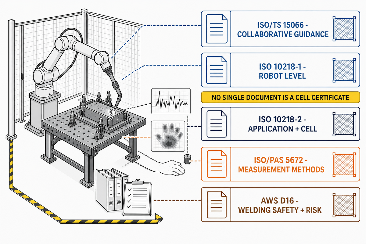
Распространённая ошибка при оценке рисков применения — воспринимать промышленный стандарт как маркировку продукции. В записи ISO в каталоге для ISO/TS 15066:2016 документ по-прежнему указан как опубликованный и действующий, хотя этап его жизненного цикла обозначен как подлежащий пересмотру. Этот статус не подтверждает соответствие требованиям конкретной сварочной ячейки.
| Документ | Практическая роль в проекте со сварочным коботом | Важное ограничение |
|---|---|---|
| ISO/TS 15066:2016 | Рекомендации по безопасности систем с коллаборативными роботами, включая критерии контакта при ограничении мощности и силы | Дополняет общую систему требований безопасности промышленных роботов; не является сертификатом сварочной ячейки |
| ISO 10218-1:2025 | Проектирование робота и информация для интеграции | Соответствие робота требованиям не доказывает безопасность интегрированного сварочного применения |
| ISO 10218-2:2025 | Применение и интеграция ячейки, пусконаладочные работы, эксплуатация, техническое обслуживание и вывод из эксплуатации | Точные редакции стандартов зависят от проекта и юрисдикции |
| ISO/PAS 5672:2023 | Методы измерения и анализа силы и давления при контакте человека с роботом | Не позволяет определить, какие опасности или сценарии контакта следует учитывать при оценке рисков |
| AWS D16.1:2018 и D16.3:2026 | Стандарты и рекомендации по безопасности сварки и оценке рисков роботизированной дуговой сварки | Применяйте, если этого требуют договор или юрисдикция; не считайте краткое описание из каталога нормативным текстом |
Проверка статуса, а не юридическое заключение
Редакции ISO 10218-1 и ISO 10218-2 за 2025 год были опубликованы в феврале 2025. Перед испытаниями уточните редакции, указанные покупателем, специалистом по оценке рисков, местным регулирующим органом и в процедуре подтверждения соответствия.
В этом наборе стандартов техническая спецификация содержит рекомендации по безопасности коллаборативных роботов, а ISO 10218 устанавливает более широкие требования к безопасности промышленных роботов и их применению. При совместной работе также могут применяться такие меры, как контролируемый останов с функцией безопасности или контроль скорости и разделения. Эти методы отличаются от ограничения мощности и силы; маркировка «коллаборативный робот» или «соответствует стандартам безопасности» сама по себе не определяет подходящий метод.
Терминология, влияющая на испытания
Манипулятор робота, функции безопасности, концевой инструмент, свариваемое изделие, сварочное приспособление и задача человека образуют единую систему применения. Поэтому безопасность применения промышленного робота нельзя свести к настройкам скорости и силы манипулятора.
Уточните формулировки запроса коммерческого предложения до выбора испытания
В спецификациях часто смешивают стандарты безопасности роботов, описания продукции и сокращённые формулировки из систем управления. Рассматривайте приведённые ниже выражения как повод определить область применения, редакцию, доказательства и ответственность, а не как подтверждение применимости требования или уже установленного соответствия требованиям безопасности.
| Формулировки в технических требованиях | Вопрос, на который должен ответить проект |
|---|---|
| «Роботы и роботизированные устройства», «промышленные роботы и их интеграция», «применение коллаборативных роботов», «ячейка с коллаборативным роботом», «6-осевой шарнирный робот» или «полезная нагрузка коллаборативного робота» | Какие именно робот, технологическая оснастка, полезная нагрузка, границы ячейки и задачи человека входят в оценку? |
| «функциональная безопасность», «требования к функциональной безопасности», «система безопасности», «функции безопасности», «остановка робота» или «робот замедляется или останавливается» | Какие функции безопасности, режимы работы, целевые показатели, методы проверки и реакции на неисправности требуются? |
| «защитные ограждения», «лазерный сканер безопасности», «ISO 13855» или «расстояние между роботом и человеком» | Какую опасность, связанную с доступом или разделением, необходимо контролировать и какие редакция стандарта и измеренная компоновка обосновывают это решение? |
| «в соответствии с ISO 12100», «в соответствии с ISO 13849-1», «стандарты безопасности роботов» или «соответствие требованиям безопасности» | Кто подтверждает применимость, принятую редакцию, юрисдикцию, комплект доказательств и полномочия по утверждению? |
| «четыре режима совместной работы», «контакт с человеком», «контакт между роботом и человеком», «рекомендации по применению коллаборативных роботов» или «Universal Robots» | Обозначает ли выражение метод работы, сценарий контакта, оборудование общего назначения или конкретный бренд — и какие доказательства применимости следуют из этого различия? |
Цепочка принятия решения по пределам силы из 7 узлов
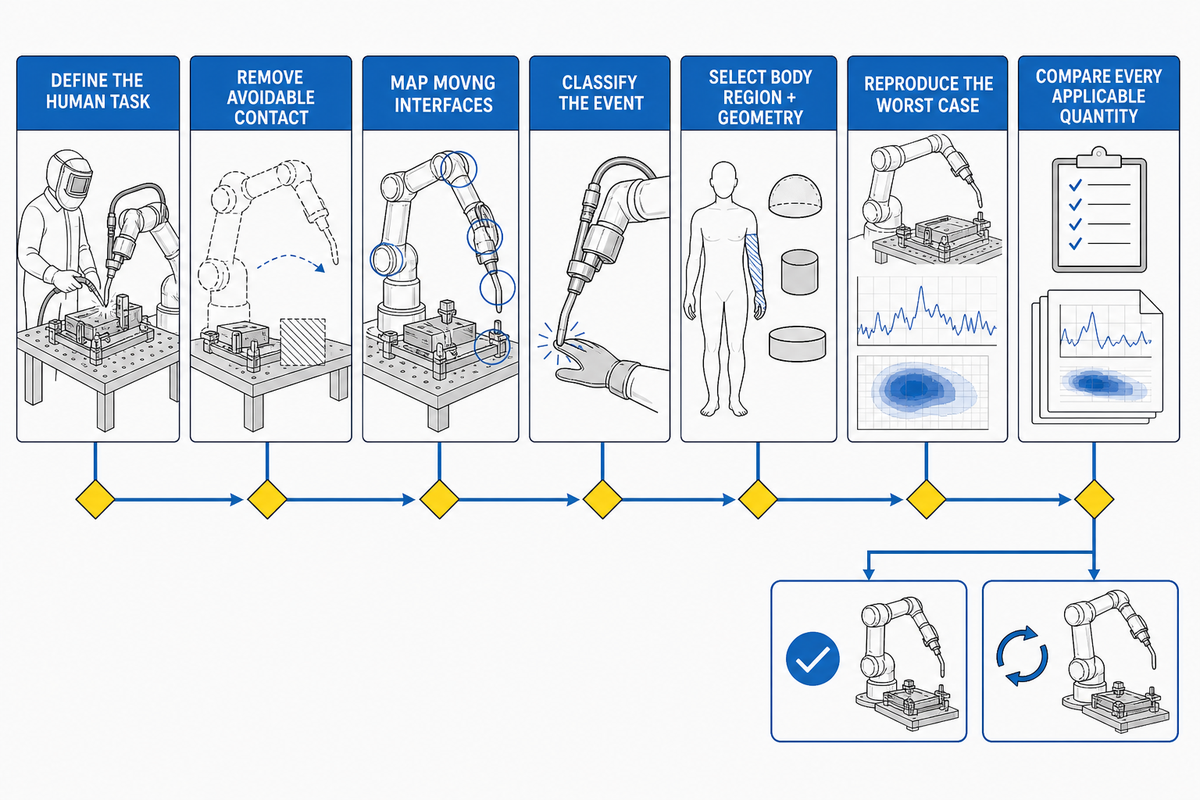
Предельные значения — последний шаг в цепочке принятия решений, а не первый. Если команда начинает с вопроса «Какое значение силы можно задать?», она пропускает вопросы, от которых зависит допустимость контакта и применимый критерий.
- Определите задачи человека, включая производство, загрузку, обучение, отладку, техническое обслуживание, ремонт и повторную калибровку.
- Устраните предотвратимые контакты, изменив планировку, доступ, сварочные приспособления, последовательность операций или защитные меры, прежде чем обосновывать допустимость контакта числовым значением.
- Определите все движущиеся элементы взаимодействия: манипулятор, сварочную горелку, проволоку, кабельную оснастку, свариваемое изделие, позиционер, сварочное приспособление и перемещаемую деталь.
- Классифицируйте событие: может ли человек отпрянуть при кратковременном ударе или может оказаться зажатым при квазистатическом контакте.
- Выбирайте область тела и геометрию контакта: широкая поверхность с мягкой накладкой и узкая кромка свариваемого изделия создают разное распределение давления.
- Зафиксируйте и воспроизведите наиболее неблагоприятный сценарий, записав полезную нагрузку, инструмент, траекторию, скорость, радиус действия, направление, эффективную массу, сварочное приспособление и поверхность, с которой происходит контакт.
- Сравните все применимые величины. Если выбранные критерии задают ограничения по силе и давлению, оба показателя должны соответствовать требованиям; в противном случае измените конструкцию контактирующих элементов или установите дополнительные защитные устройства.
Заблуждение о двух числах
Значения силы и давления не являются универсальными настройками для всей ячейки. Каждое значение относится к определенному сценарию контакта, области тела, классификации контакта, геометрии, конфигурации испытания и редакции применимых критериев.
Правило двух критериев для применимых контактов PFL
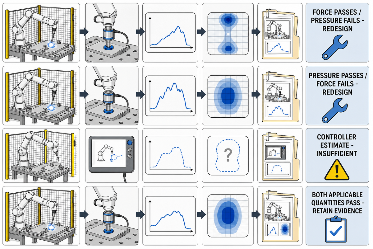
Сила характеризует общее взаимодействие, а давление во многом зависит от площади и формы поверхности, на которую действует эта сила. Широкая податливая прокладка может снизить пиковое давление, не обязательно уменьшая общую силу; узкий кронштейн сварочной горелки или угол свариваемого изделия может концентрировать давление, даже если показания силы невелики.
«Если превышен предел силы или давления, требования не выполнены».
Рекомендации DGUV FB HM-080 для роботизированных систем с ограничением мощности и силы
| Наблюдаемый результат | Что подтверждает | Решение |
|---|---|---|
| Применимое значение силы в допустимых пределах, давление — нет | Энергия может контролироваться, но геометрия по-прежнему концентрирует нагрузку | Не соответствует требованиям; измените форму контактной поверхности, добавьте прокладку, увеличьте зазор, измените траекторию или установите защитное ограждение |
| Давление в допустимых пределах, применимое значение силы — нет | Контакт распределен по большей площади, но общее взаимодействие по-прежнему чрезмерно | Не соответствует требованиям; снизьте энергию, скорость, эффективную массу или продолжительность воздействия |
| Оценка силы контроллером ниже заданного значения | Только то, что контроллер выдал свою оценку в ходе данного запуска | Недостаточно без измерения контакта для конкретного сценария |
| Оба применимых показателя соответствуют требованиям | Испытания подтвердили соответствие контакта зафиксированным условиям | Сохраните подтверждающие данные и продолжите оценку всех остальных опасностей применения |
Это уточнение важно. В материалах семинара NIST по биомеханическим пределам отмечается, что начало болевых ощущений можно описать такими показателями, как сила или нормальное напряжение, а форма ударного элемента влияет на достоверность результатов. Применяйте правило прохождения обоих критериев, если выбранные критерии PFL устанавливают оба предела; не представляйте это как универсальное требование без подтверждения.
Границы авторских прав и точности
В этом руководстве не приводится полная таблица предельных значений ISO/TS 15066, приложение A. Выбирайте авторитетные значения из лицензированного стандарта и редакций, принятых для проекта; избегайте общих утверждений, таких как «150 N» или «65 N», без указания соответствующего участка тела и условий контакта.
Классифицируйте каждый контакт с помощью матрицы испытаний по карте контактов
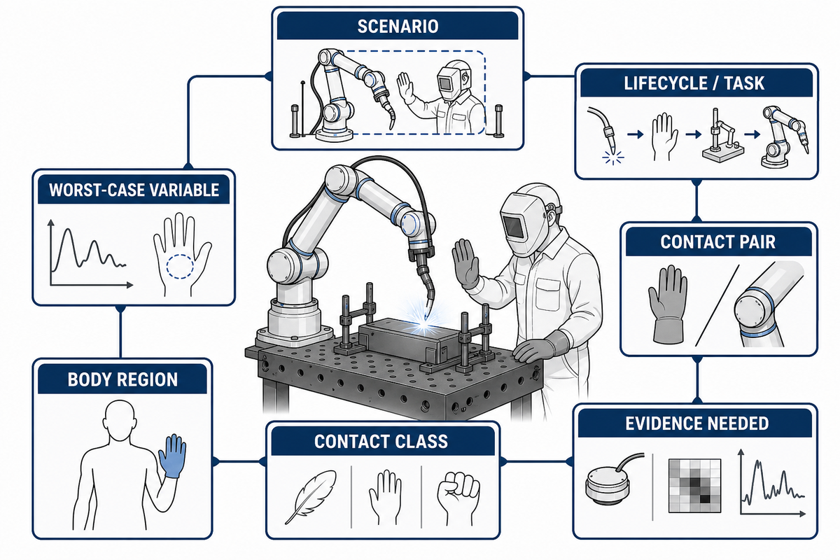
Свободные удары и защемление — не одно и то же. Используйте эту матрицу как шаблон планирования, а не как готовую запись о соответствии требованиям; замените каждую строку данными о реальных задачах, поверхностях, участках тела, конфигурациях, критериях и измерениях для конкретного применения.
| Сценарий | Этап жизненного цикла/задача | Пара контактирующих элементов | Класс | Вероятная область тела | Переменная наихудшего сценария | Необходимые доказательства |
|---|---|---|---|---|---|---|
| CM-01 | Загрузка | Манипулятор и оператор | Кратковременный контакт | Кисть/рука | Максимальная достижимая скорость | Пиковое значение по записи измерений и геометрия |
| CM-02 | Загрузка | Манипулятор и сварочное приспособление | Квазистатический | Кисть/палец | Минимальный зазор | Условия измерения силы, давления и защемления |
| CM-03 | Наблюдение за производством | Корпус сварочной горелки и человек | Кратковременный контакт | Рука/туловище | Ориентация инструмента и радиус действия | Контактное приспособление и исходная запись |
| CM-04 | Извлечение детали | Горячее свариваемое изделие и оператор | Опасность, связанная с технологическим процессом | Кисть/рука | Температура детали | Контроль температуры, а не предел PFL |
| CM-05 | Обучение | Манипулятор и неподвижная конструкция | Квазистатический | Кисть/рука | Траектория и скорость в ручном режиме | Документ о защитных мерах для каждого режима |
| CM-06 | Отладка | Кабельная оснастка и человек | Кратковременный контакт | Верхняя часть тела | Неожиданное движение кабеля | Проверка на предсказуемое неправильное использование |
| CM-07 | Замена наконечника | Проволока/электрод и кисть | Опасность контакта с острыми кромками | Кисть/палец | Открытая точка и накопленная энергия | Документ об устранении опасности или установке защитного ограждения |
| CM-08 | Техническое обслуживание | Ось и сварочное приспособление | Квазистатический | Кисть руки/туловище | Неожиданное движение | Процедура отключения и изоляции источников энергии |
| CM-09 | Ремонт | Сварочный позиционер и техник | Раздавливание/защемление | Всё тело | Гравитация и накопленная энергия | Способ отключения и блокировки источников энергии |
| CM-10 | Повторная калибровка | Движущийся инструмент и технический специалист | Кратковременный или квазистатический контакт | Для конкретной задачи | Временная установка | Измененный сценарий и результат приемки |
Приоритет при проектировании
Не считайте предвидимый контакт с головой или шеей нормальным только потому, что в таблице, по-видимому, указано допустимое значение. По возможности исключите доступ к опасным зонам с риском тяжёлых травм с помощью компоновки, зазоров, последовательности операций, блокировок, контролируемых зон или других мер управления рисками.
Как подготовить обоснованный план проверочных испытаний
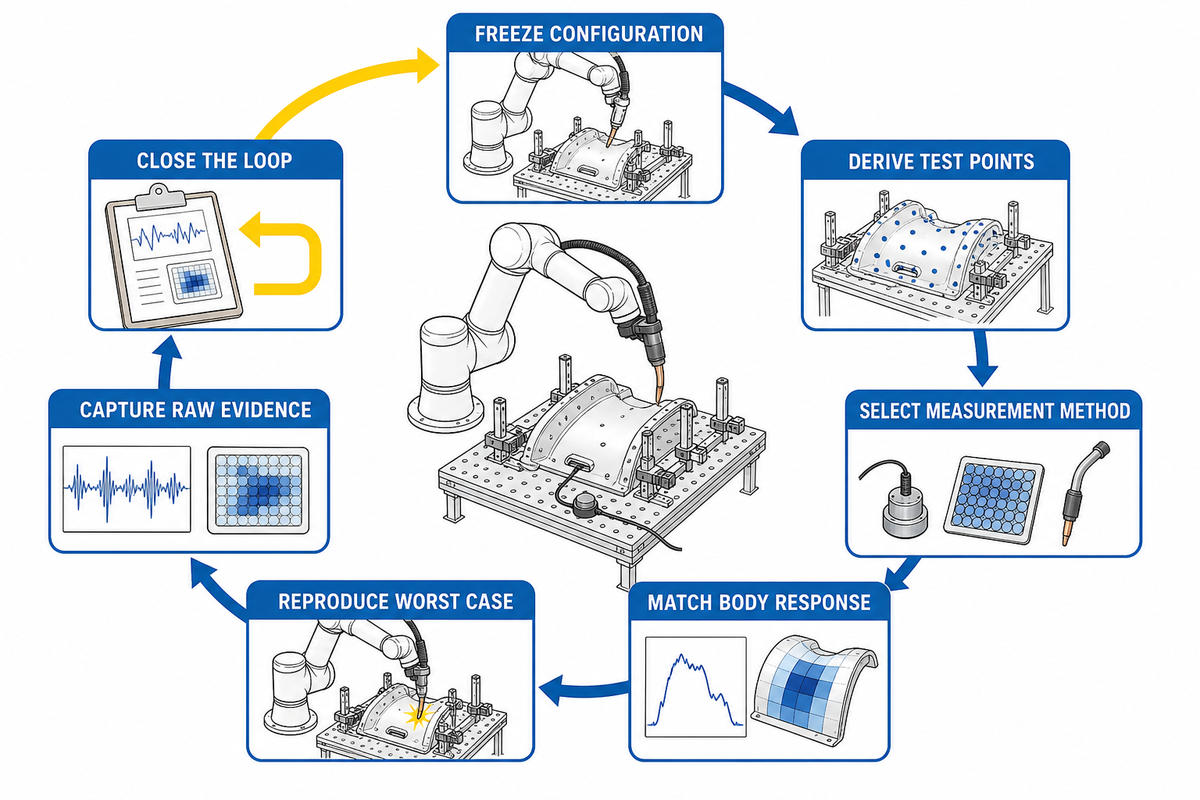
Карта контактов определяет, что должно воспроизводить достоверное испытание: оцениваемый контакт, соответствующую реакцию тела и энергию применения в наихудшем сценарии. Снимки экрана контроллера не показывают локальное давление, геометрию защемления, реакцию прибора или соответствие испытанной программы и полезной нагрузки производственным условиям.
- Зафиксируйте перечень конфигурации. Укажите робот, полезную нагрузку, сварочную горелку, проволоку, прокладку кабелей, свариваемое изделие, сварочное приспособление, позиционер, версию программы, параметры безопасности и компоновку ячейки.
- Определите точки испытания на основе оценки рисков. Удобные точки на манипуляторе не заменяют поверхности, с которыми человек действительно может соприкоснуться.
- Выберите метод измерения. В каталоге ISO/PAS 5672:2023 описана область применения документа: методы испытаний силы и давления, а также характеристики устройств.
- Сопоставьте реакцию тела с результатами моделирования. Для выбранного сценария задокументируйте биофиделический элемент, область контакта, крепление, идентификационные данные прибора, калибровку и пригодность.
- Воспроизведите наихудший сценарий. При зафиксированной конфигурации проверьте радиус действия, направление, скорость, эффективную массу, поведение при остановке, зазор в зоне защемления и контактную поверхность.
- Сохраните исходные данные. Зафиксируйте записи измерений силы и давления, частоту сбора данных, фильтрацию, повторы, неопределённость, фотографии испытательной установки и метод анализа.
- Замкните цикл. Если критерий не выполнен, измените энергию, геометрию, поверхность, траекторию, зазор или защитные меры, затем повторите соответствующее испытание и утвердите итоговый результат.
Журнал передачи результатов проверки из девяти записей
Результаты валидации становятся пригодными для повторного использования как проектные данные только тогда, когда протокол испытаний связывает оцененный сценарий с утвержденной конфигурацией. В следующем реестре отдельно указаны записи, необходимые для воспроизведения результата, и события, при которых оценку следует провести повторно.
| Контрольный пункт | Подтверждающие данные о соответствии требованиям | Повторную оценку следует провести, если |
|---|---|---|
| Оцененная задача | Указанная производственная или непроизводственная операция | Изменение задачи, маршрута доступа или группы пользователей |
| Сценарий контакта | Пара контактирующих поверхностей, область тела и условия защемления | Изменения геометрии или зазоров |
| Настройка робота | Изменения робота, контроллера, встроенного ПО и средств безопасности | Изменяются программное обеспечение, контроллер или настройки безопасности |
| Концевой инструмент | Запись о сварочной горелке, адаптере, проволоке и кабельной оснастке | Изменяются масса, форма или прокладка кабелей инструмента |
| Закрепление свариваемого изделия | Идентификация свариваемого изделия, сварочного приспособления и позиционера | Изменяется деталь, сварочное приспособление или позиционер |
| Движение | Программа, траектория, скорость, радиус действия и направление | Изменяются программа или темп производства |
| Настройка измерительного прибора | Идентификационные данные прибора, калибровка, крепление и сведения о фильтрации | Изменение измерительного прибора или метода анализа |
| Результат измерения | Исходные записи измерений, повторы, неопределённость и решение о соответствии критериям | Повторное испытание недействительно или критерий изменился |
| Утверждение | Указанные проверяющий, незакрытые действия, остаточные риски и дата допуска к эксплуатации | Появилось незакрытое действие или сработал триггер контроля изменений |
Примечание об измерениях
В рекомендациях DGUV описана стационарная измерительная система и сбор данных с частотой не менее 1 kHz для сигналов с частотой до 100 Hz с заданной фильтрацией. Рассматривайте это как рекомендацию по практике, относимую к DGUV, а не как вымышленную цитату из ISO/TS 15066; применяйте метод, предусмотренный лицензированными документами проекта и планом испытаний.
Положительный результат испытания контакта не означает, что сварка безопасна
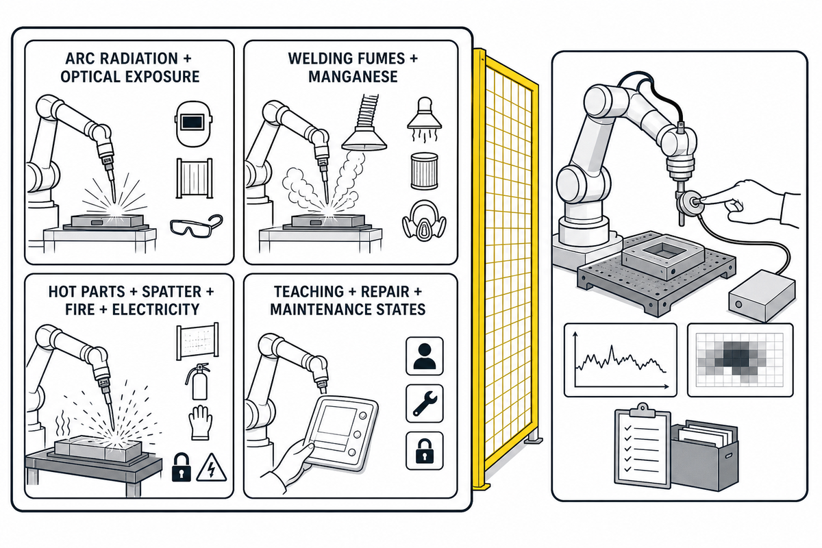
Ограничение мощности и силы применяется к оцененному контакту человека с роботом. Помимо этого плана испытаний, сварка создает дополнительные опасности, поэтому оценка рисков должна отдельно учитывать дугу, сварочные аэрозоли, электрическую энергию, нагрев, брызги, острые кромки проволоки и свариваемого изделия, сварочные приспособления, позиционеры, цилиндры и накопленную энергию.
| Данные PFL могут подтвердить | Данные PFL не позволяют подтвердить | Примеры отдельных защитных мер |
|---|---|---|
| Удар или сдавливание при контакте в оцененном сценарии | Защита от излучения сварочной дуги и оптического излучения | Экраны для защиты от сварочной дуги, контролируемый доступ, средства индивидуальной защиты |
| Соответствие применимым критериям силы и давления | Контроль сварочных дымов и воздействия марганца | Выбор способа сварки, местная вытяжная вентиляция, оценка воздействия |
| Испытанная геометрия и конфигурация движения | Защита от горячих деталей, брызг расплавленного металла, пожара и поражения электрическим током | Тепловые барьеры, порядок на рабочем месте, электрические защитные меры, контроль огневых работ |
| Остаточные риски контакта, указанные в досье | Безопасность непроверенных режимов обучения, ремонта или технического обслуживания | Процедуры для каждого режима, отключение и изоляция источников энергии, блокировка, надзор и контроль доступа |
В техническом руководстве OSHA по промышленным роботизированным системам отдельно рассматриваются опасности системы, режимы выполнения задач и ответственность на протяжении жизненного цикла. NIOSH также рассматривает воздействие сварочных дымов и марганца как профессиональную опасность, зависящую от процесса, а не как предел контакта с роботом.
Слой стандартов для сварки
В каталоге комитета AWS D16 указаны D16.1M/D16.1:2018 по безопасности роботизированной дуговой сварки и D16.3M/D16.3:2026 по оценке рисков роботизированной дуговой сварки. Применяйте соответствующие документы AWS вместе с оценкой рисков применения робота и проверкой контактов, а не вместо них.
Подтверждение соответствия и триггер управления изменениями
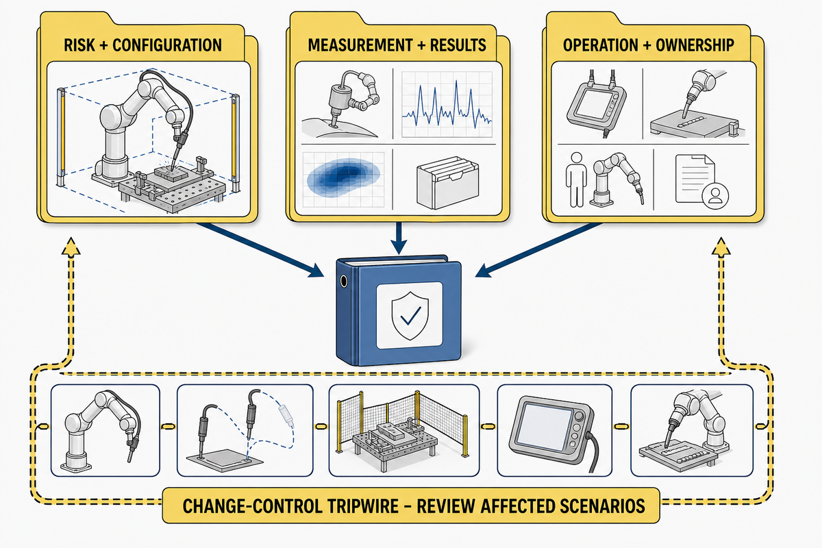
При передаче проекта итог не должен сводиться к фразе «кобот соответствует требованиям». В полезном комплекте приемочной документации указаны оцененная конфигурация применения и сценарии контакта, методы испытаний, полученные результаты, сохраняющиеся остаточные риски и изменения, после которых оценку нужно провести заново.
Риски и конфигурация
- Подписанная оценка рисков и матрица сценариев
- Изменения робота, инструмента, полезной нагрузки, свариваемого изделия, сварочного приспособления, программы и средств безопасности
- Производственные и непроизводственные режимы работы
Измерения и результаты
- Идентификация прибора и калибровка
- Фотографии настройки, исходные записи силы и давления, метод анализа
- Применимые пределы, результат, погрешность, корректирующие действия и утверждение
Работа и ответственность
- Валидация функций безопасности и инструкции по остаточным рискам
- Назначенный ответственный за приемку на площадке и дальнейшее техническое обслуживание
- Основания для запуска контроля изменений и ответственность за повторную валидацию
Кто отвечает за какие подтверждающие данные?
| Роль | Ответственность за предоставление подтверждающих данных, определяемая в проекте |
|---|---|
| Производитель робота | Ограничения робота, функции безопасности, сведения об интеграции и инструкции по техническому обслуживанию. При проверке поставщика ознакомьтесь с профилем производителя сварочных систем. |
| Системный интегратор | Оценка рисков конкретного применения, проектирование защитных мер, контроль конфигурации, валидация и техническая документация. Определите границы ячейки с учетом конфигурации системы с коллаборативным роботом. |
| Работодатель/пользователь | Условия на площадке, процедуры, обучение, надзор, проверки, техническое обслуживание и управление изменениями. Сопоставьте эти обязанности с документально подтвержденным объемом работ поставщика. |
| Операторы и специалисты по техническому обслуживанию | Знание задач, предвидимое неправильное использование, потребности в доступе, выявленные опасности и участие в проверке. Соотнесите эти задачи с предлагаемой системой роботизированной сварки. |
| Полномочия по утверждению | Подписанное решение по результатам, отклонениям, остаточным рискам, незакрытым действиям и разрешению на ввод ячейки в эксплуатацию. |
Что запускает триггер контроля изменений?
- Сварочная горелка, электрод, концевой исполнительный элемент или адаптер
- Полезная нагрузка, свариваемое изделие, сварочное приспособление или позиционер
- Прокладка кабелей или шлангов
- Траектория, скорость, радиус действия, направление или параметр безопасности
- Компоновка ячейки, доступ, экран, ограждение или контролируемая зона
- Робот, контроллер, встроенное ПО или программное обеспечение безопасности
- Ремонт, влияющий на остановку или поведение при контакте
- Новая производственная задача, обучение, очистка или техническое обслуживание
Объем повторной валидации следует ограничить затронутыми сценариями, а решение необходимо задокументировать. Изменение, влияющее на скорость, эффективную массу, геометрию, зазор в зоне защемления, доступ или характер задачи, может сделать результат недействительным, даже если модель робота не изменилась.
Привязка к конфигурации — именно это и означает
Положительный результат испытания относится к испытанной конфигурации и сценарию. Это не универсальный сертификат для любых свариваемых изделий, сварочных горелок, программ, скоростей, роботизированных постов и задач операторов.
Система закупки по 3 критериям
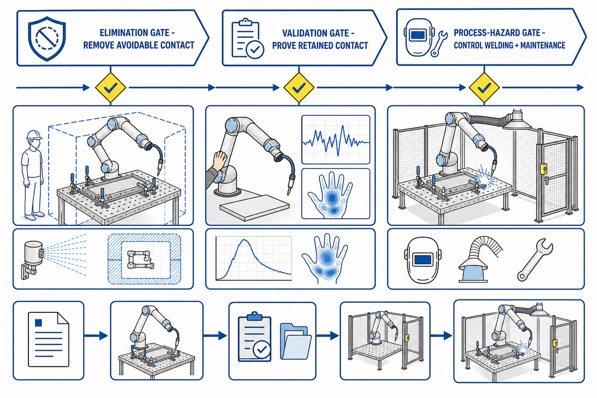
Поскольку каждый положительный результат испытаний привязан к конкретной конфигурации, заказчикам следует включать в закупку объем работ по интеграции и протокол приемки, а не только манипулятор коллаборативного робота. Эти три контрольных этапа помогают сосредоточить запрос ценового предложения на данных, которые сохранят актуальность после пусконаладочных работ и последующих изменений.
- Проверка возможности устранения опасности: Можно ли конструктивно исключить контакт, точку защемления, открытую острую кромку или опасный доступ?
- Контрольный критерий: Можно ли воспроизвести, измерить и задокументировать каждый сохраняющийся контакт и подтвердить его соответствие требованиям для наиболее неблагоприятной реалистичной конфигурации?
- Контрольный критерий по опасностям процесса: Независимо ли контролируются опасности сварки и технического обслуживания и включены ли эти меры в приемку на площадке?
Включите эти пункты в запрос коммерческого предложения
- Требуемые стандарты ISO, AWS, национальные стандарты и стандарты заказчика с указанием редакций
- Распределение обязанностей между производителем, интегратором, работодателем/пользователем, работниками и органом приемки
- Перечень сценариев контакта при производстве и вне его
- Метод измерения, измерительные приборы, калибровка, формат исходных данных и неопределенность
- Меры защиты при сварочном процессе, валидация функций безопасности и документирование остаточных рисков
- Формат комплекта документов для приёмки, порядок утверждения, условия запуска управления изменениями и ответственный за повторную проверку
При сравнении систем роботизированной сварки с коллаборативным роботом уточните, какие данные по конкретному применению поставщик передаст вместе с ячейкой. Технические характеристики изделия служат исходными данными для интеграции, но не заменяют итоговую оценку рисков и приемочные испытания.
Обсудите применение до определения объёма приёмки
Предоставьте сведения о свариваемых изделиях, сварочных приспособлениях, задачах оператора, требуемом доступе, способе сварки и планируемых условиях переналадки. Эти данные определяют, можно ли исключить контакт и что потребуется проверить.
Ознакомьтесь с решением на базе коллаборативного сварочного роботаЧасто задаваемые вопросы
Остаётся ли ISO/TS 15066 актуальным после выхода ISO 10218:2025?
Посмотреть ответ
Да. По состоянию на August 13, 2026 ISO указывает ISO/TS 15066:2016 как опубликованный и действующий стандарт, для которого запланирован пересмотр. ISO 10218-1:2025 и ISO 10218-2:2025 также опубликованы. Уточните, какие связанные редакции приняты для проекта, вместо того чтобы считать ISO/TS 15066 отозванным, и зафиксируйте выбор редакций в оценке рисков и плане испытаний.
Делает ли соответствие кобота требованиям ISO 10218-1 соответствующей требованиям всю роботизированную сварочную ячейку?
Посмотреть ответ
Нет. ISO 10218-1 устанавливает требования к роботу, тогда как интегрированное применение имеет собственную компоновку, инструменты, свариваемые изделия, сварочные приспособления, программы, доступ, технологические опасности и задачи. Эти условия по-прежнему требуют оценки рисков, защитных мер, валидации и документированного подтверждения соответствия при приемке. Сварочная горелка, кабельная оснастка, горячая деталь, острая проволока, позиционер и неподвижные ответные поверхности могут создавать опасности, которые не отражены в декларации модели робота. Рассматривайте документацию на робота как один из исходных материалов для принятия решения на уровне ячейки.
Нужно ли измерять давление, если кобот показывает силу или крутящий момент?
Посмотреть ответ
Расчетная оценка контроллера не устанавливает локальное давление. Если выбранные критерии контакта предусматривают ограничение давления, измерьте его подходящим методом с учетом области тела, геометрии и типа контакта; отдельно измерьте необходимую силу, а не выводите одно значение из другого. При одинаковой общей силе широкая поверхность и узкая кромка могут давать разные значения давления. Задокументируйте измерительное устройство, биомиметический элемент, площадь контакта, калибровку, метод сбора и фильтрации данных, повторные измерения, исходные кривые и испытанную конфигурацию. Если любое из применимых значений выходит за пределы, измените энергию, геометрию, зазор, траекторию или защитную меру и повторите соответствующее испытание.
Когда следует повторно оценивать безопасность сварочного кобота?
Посмотреть ответ
Повторно подтвердите безопасность затронутых сценариев после изменений, способных повлиять на энергию контакта, геометрию, защемление, доступ, остановку или выполнение задачи. К типичным причинам относятся замена сварочной горелки, полезной нагрузки, свариваемого изделия, сварочного приспособления, укладки кабелей, программы, скорости, параметра безопасности, компоновки, ремонт, обновление программного обеспечения или изменение задачи оператора либо специалиста по техническому обслуживанию.
Может ли сварочный кобот работать без ограждения?
Посмотреть ответ
Только если оценка рисков конкретного применения обосновывает выбранный режим совместной работы и все соответствующие опасности контролируются. Наличие манипулятора с ограничением силы не отменяет необходимости в защитных экранах от дуги, контроле сварочных аэрозолей, ограничении доступа, блокировках, контролируемых зонах, стационарных ограждениях или других защитных мерах, если они требуются сварочным процессом и конструкцией ячейки. Поэтому обоснованная компоновка может сочетать средства защиты для совместной работы с традиционными защитными мерами.
Сначала определите, какие доказательства нужны, затем задавайте скорость
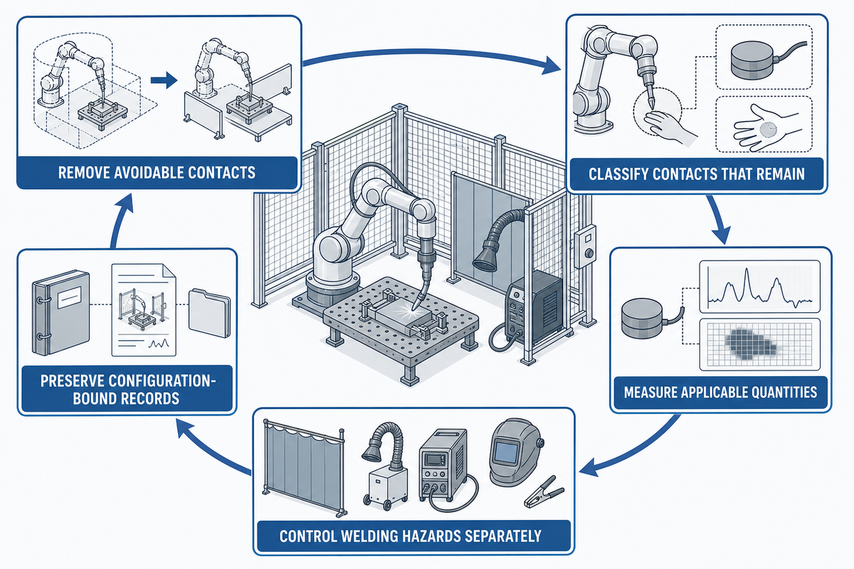
ISO/TS 15066 не требует от покупателя безоговорочно принимать маркировку «безопасный кобот». Команда проекта должна принимать решения с учетом конкретного применения: исключить предотвратимые контакты, классифицировать оставшиеся, измерить необходимые параметры в наихудших условиях, отдельно контролировать опасности сварки и вести записи, привязанные к конфигурации.
Вопрос для окончательной приемки
Если завтра изменятся сварочная горелка, свариваемое изделие, сварочное приспособление, траектория, скорость, программное обеспечение, доступ или задача, смогут ли ваши записи точно показать, какие сценарии нужно пересмотреть и испытать повторно? Если нет, у проекта есть настройка силы, но нет обоснованной системы подтверждения безопасности.
Об этом руководстве по безопасности
Wuxi Zhouxiang Complete Set of Welding Equipment Co., Ltd. разрабатывает и поставляет системы автоматизации сварки, включая решения для коллаборативной сварки. В этой статье проверка контакта с роботом отделена от контроля сварочного процесса, чтобы покупатели могли четко определить объем приемки. Подробнее о команде и производственной базе можно узнать в профиле компании.
Ссылки и источники
- ISO/TS 15066:2016, коллаборативные роботы, Международная организация по стандартизации
- ISO 10218-1:2025, промышленные роботы, Международная организация по стандартизации
- ISO 10218-2:2025, промышленные робототехнические системы и роботизированные ячейки, Международная организация по стандартизации
- ISO/PAS 5672:2023, методы испытаний для измерения силы и давления, Международная организация по стандартизации
- FB HM-080: коллаборативные робототехнические системы с ограничением мощности и силы, DGUV
- Мягкие датчики силы и давления для применения в системах безопасности роботов, Национальный институт стандартов и технологий
- Промышленные робототехнические системы и безопасность промышленных робототехнических систем, Управление по охране труда
- Сварочные аэрозоли и марганец, Национальный институт охраны труда
- Комитет D16 по роботизированной и автоматизированной сварке, Американское общество сварщиков