Get in Touch with Zhouxiang

Rotary Positioner Welding Robot Selection: An Engineering Guide

Contents
show
COORDINATED EXTERNAL-AXIS ENGINEERING GUIDE
For a robotic positioner or rotary welding positioner, rotary positioner welding robot selection should not begin with load numbers in a catalog. To select a positioner, the selection should start with the complete moving load and weld path. A defensible choice should consider the fixture, center of gravity, eccentric load, inertia, robot reach, controller integration, production flow and the evidence you will witness before acceptance.
Three pages, three jobs: this guide covers a positioner used as a robot’s coordinated external axis. If you are still comparing broad positioner families, use the welding positioner selection guide. If you need commercial configurations and system options, visit the cantilever welding robot page. Keeping these intents separate helps each page answer one buyer decision well.
The main idea is the Load-to-Path Selection Chain. To qualify the part family, you determine the combined load. Next, you select the motion mode and prove reach. Lastly, you accept the cell within a declared test envelope. Skipping any of these steps can lead to a positioner that holds the part, but is not able to move the part accurately, safely, or quickly enough to satisfy the requirements of the weld.
Start With the Weldment, Not the Positioner Rating
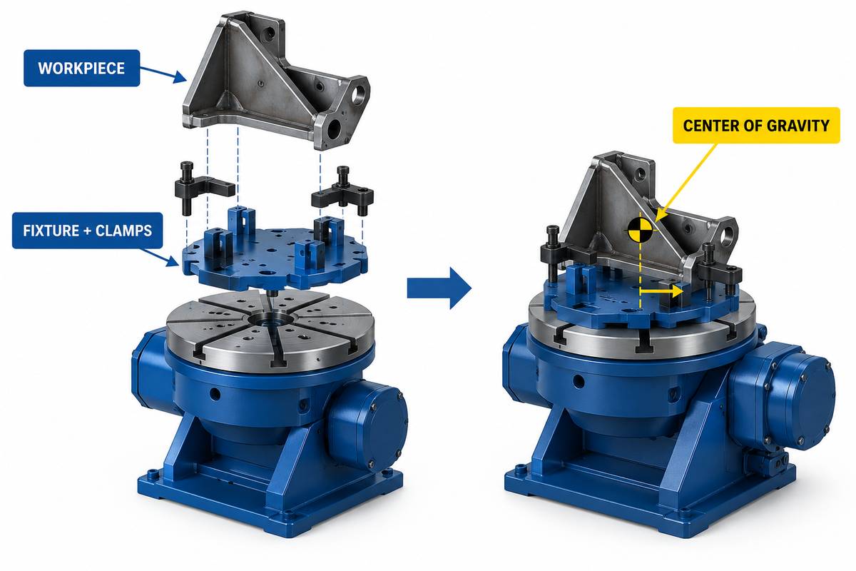
You build a part family envelope before requesting a physical part model. When defining an envelope, include the lightest and heaviest production parts, the fixture and chuck, the overall dimensions, the loading orientation, the weld locations, expected fit-up variation, and all temporary items that rotate with the assembly.
The Association for Advancing Automation’s positioner overview, likewise, frames selection around the workpiece, required motion and the robot-cell integration. This guide incorporates these inputs and extends them to a buyer-controlled evidence chain.
In considering a range of options, you should use the worst case configuration of the production parts. Nominal parts are not acceptable if a gusset, clamp, or adapter plate shifts the center of gravity away from the axis.
| Qualification field | What to record | Why it changes selection |
|---|---|---|
| Part family | Drawing revisions, size range, material, joint map | Defines the real motion and reach envelope. |
| Complete moving load | Part, fixture, chuck, clamps, adapters, cables | Prevents sizing from workpiece weight alone. |
| Combined center of gravity | Offsets from rotation and tilt axes in all required orientations | Drives static moment and bearing load. |
| Weld path | Seam geometry, torch angles, preferred weld position | Determines indexing versus coordinated motion. |
| Production pattern | Batch size, takt target, changeover, loading method | Shapes station count, speed, and flow. |
| Acceptance rule | Inspection method, sample identity, pass criteria | Turns a demonstration into controlled evidence. |
A part family is a poor automation candidate when the datums are unstable, the center of gravity is unknown, fixtures change without revision control, or critical joints can’t be reached without eccentric torch angles. Work on those inputs and consider treating a larger positioner as the answer.
Build the Combined-Load and Motion Worksheet
The first calculation is simple: Add all the movable parts. The engineering assessment is not so straightforward. The same total mass creates different moments and inertia, based on where the total mass is distributed, and how quickly the axis of rotation accelerates.
Screening equations—not final equipment ratings
Combined mass: m total = m part + m fixture + m chuck + m attachments .
The simple eccentric gravity moment is given by M = mtotal x g x e, where e is the perpendicular offset from the axis. For tilt motion, use the worse case required orientation.
These equations screen the application. Final selection must use the manufacturer’s allowable load, moment, torque, inertia, speed, acceleration, braking, duty-cycle, and mounting limits for the proposed configuration.
| Worksheet input | Worst-case value | Supplier evidence requested | Owner |
|---|---|---|---|
| Total moving mass | Heaviest released assembly | Rated-load chart at actual orientation | Mechanical engineering |
| CG height and radial offset | Largest verified offset | Allowable moment/load-envelope chart | Fixture designer |
| Required rotational speed | Fastest process or index move | Speed under declared load and duty | Process engineering |
| Acceleration and braking | Cycle model plus safe stop | Motor, gearbox, brake, and controller calculation | Integrator |
| Load inertia | Worst geometry about each axis | Allowable inertia and tuning confirmation | Controls/integrator |
| Service factor | Defined by duty and uncertainty | Written sizing assumptions | Buyer and supplier |
Do not use a universal safety factor. The appropriate margin is dependent on many factors including the shock, cycle, braking, process variation, uncertainty, and the manufacturer’s rating method. Ask the supplier to state which assumptions are embedded in its calculation and which assumptions are left to you to validate.
Where repeatability or accuracy is critical, distinguish between command repeatability and application accuracy. [NIST research on robotic-system tolerances and uncertainty] is a good reference.
Decide Whether the Positioner Indexes or Moves During Welding
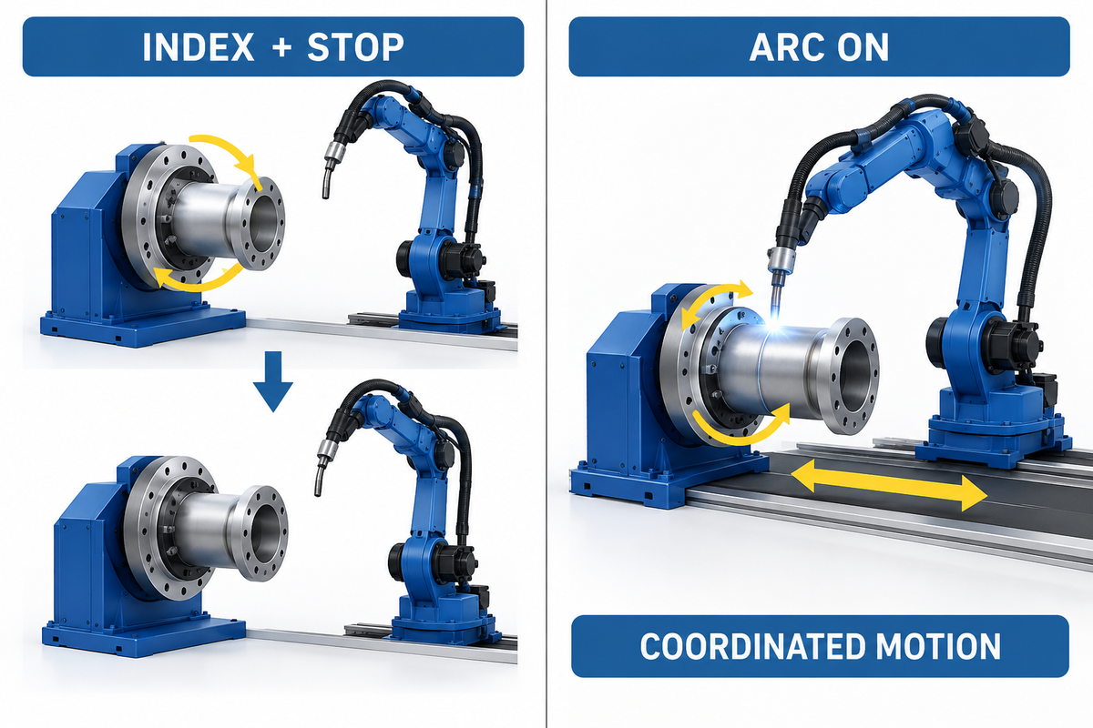
This is the most important motion decision. The A3 selection overview provides external context for matching workpiece and motion requirements. In an index-and-weld cycle, the part moves to a position, stops, and the robot completes the weld. In coordinated welding, the positioner moves while the arc is on and the robot controller treats it as an interpolated external axis.
| Weld-path condition | Likely motion mode | Additional proof needed |
|---|---|---|
| Separate seams can be completed in stable orientations | Index and weld | Index repeatability, clamp stability, stop time |
| Circumferential or long curved seam benefits from constant torch posture | Continuous coordinated rotation | Interpolation, velocity matching, seam result under load |
| Several faces require gravity-favorable welding positions | Tilt-rotate | Load envelope through all tilt angles |
| Long cylindrical or frame-like part needs support at both ends | Headstock-tailstock | Alignment, support, deflection, synchronized behavior |
| Loading overlaps welding on another station | Dual-station architecture | Operator separation, station-change time, bottleneck model |
Continuous motion changes more than just the motor. It affects servo ownership, encoder feedback, coordinate frames, path planning, recovery from interruption, cable routing, and behavior in a safe state. It also changes acceptance testing. A stand-alone turntable that is capable of rotating is not automatically a coordinated robot axis.
Select the Minimum Sufficient Motion Architecture
Architectural decisions should be deferred until motion decisions have been made. The existing positioner-family guide covers the broader type comparison that precedes this external-axis decision. A single rotary axis can be adequate for axisymmetric work whose joints become accessible through rotation. A tilt-rotate unit increases the CG and makes moment limits more critical. A headstock-tailstock arrangement supports a long, heavy part, while a dual-station system involves trade-offs in safeguarding and floor space.
Don’t choose more axes just because they are more capable. Each additional axis creates more mechanical interfaces, changes the work, adds guarding, increases maintenance and integration challenges. For a better weld, a better question is, what is the smallest number of motions controlled that places all of the required weld within the robot’s usable posture envelope?
A weld positioner guide analysis broadens our focus on buyers to include different types of positioners such as a single positioner, a 2-axis positioner, an H-frame positioner, a ferris wheel positioner, and tailstock positioners. Those labels won’t matter until the weld path establishes if a horizontal axis, vertical axis, or multi-axis weld motion is needed. When buyers choose a positioner, that boundary keeps choosing the right welding positioner from becoming a catalog exercise.
Prove Robot Reach and Welding Posture Before Buying Hardware
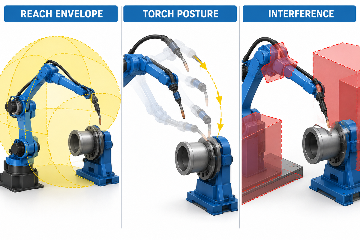
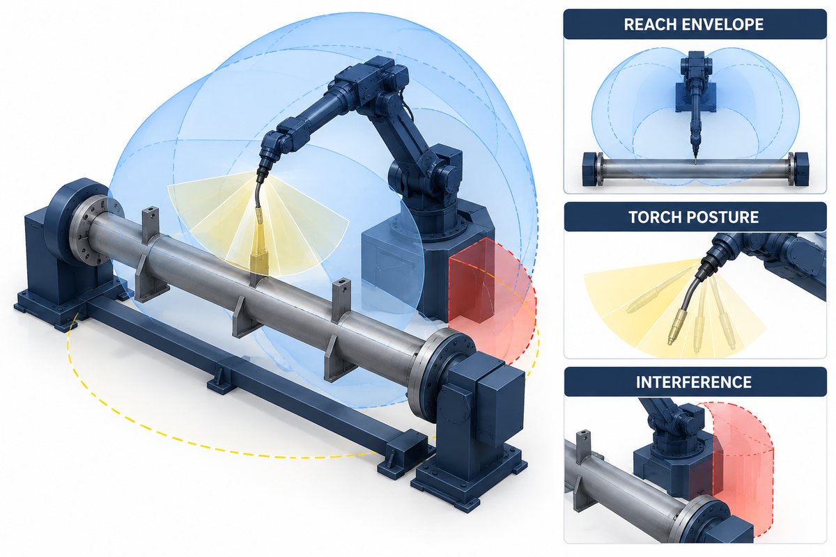
The distance is not a radius on a robot brochure. The usable envelope shrinks when a torch dress pack, fixture, clamps, extraction hardware and the required work angle are taken into account. A point on the chart may be geometrically reachable yet unsuitable because the wrist approaches a singularity, the torch angle is incorrect or the cable collides during positioner motion.
1. Use worst-case partsModel the largest, smallest, deepest, and most offset members of the family.
2. Use the real toolInclude torch geometry, adapter, sensor, dress pack, stick-out, and service envelope.
3. Exercise both axesSimulate robot and positioner through the complete coordinated path.
4. Preserve assumptionsSave model revisions, frames, interference rules, and unresolved clearances.
5. Confirm physicallyWitness a representative path with production-equivalent fixture and tooling.
You should request the signed kinematic layout and definition of axes used in the study. This is critical when product pages or proposals differ in conventions of robot, travel, rotation or positioner axes. Drawings, controller configuration and acceptance tests should be in agreement.
As shown in NIST’s calibration and registration resources, incorporating a dedicated verification step for coordinate registration is warranted. NIST does not stipulate a welding-cell interval. The project defines the verification triggers and tolerances.
Specify the Robot–Positioner Control Interface
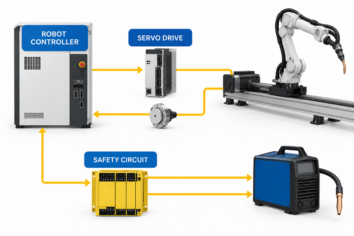
“Compatible” is not a specification. The cantilever welding robot page is the first-party configuration reference; the project still needs a written interface definition. For weld positioning systems, identify which controller owns the positioner servo, the drive and encoder used, the calibration of the coordinate systems, which safety signals cross the boundary, and the consequences of an emergency stop and interrupted weld.
Servo-driven positioners are common in modern robotic welding because the robotic system uses servo control requiring position feedback. Confirm the proposal uses integrated servo positioners for continuous coordination or a different interfaced method. The answer alters the breadth of effort required for programming, commissioning, fault recovery, and preventive maintenance of the robotic welding system.
| Interface question | Required answer | Acceptance evidence |
|---|---|---|
| Who commands motion? | Robot controller, PLC, or separate positioner controller | Architecture drawing and live demonstration |
| Is motion interpolated? | Coordinated external axis or indexed handshake | Representative seam or indexed sequence |
| How is position known? | Encoder type, homing, calibration, mastering | Recovery and position-verification test |
| What is the safe state? | Defined response to gate, E-stop, servo fault, loss of communication | Safety-function validation record |
| How does restart work? | Controlled resume, retract, rehome, or scrap/rework decision | Interrupted-cycle challenge test |
| Who owns software revisions? | Backup, access, change approval, support boundary | Handover package and restore test |
Engineer Fixtures, Grounding, and Utilities as Part of the Axis
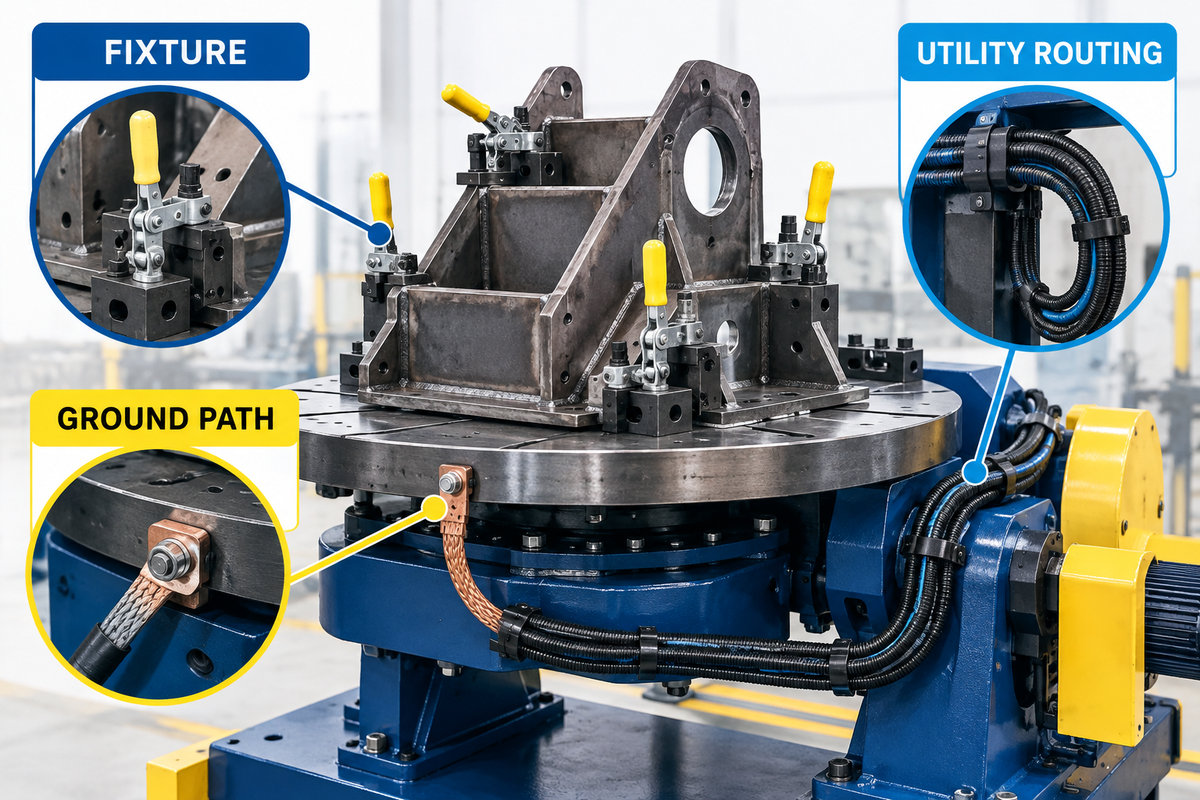
The positioner is not capable of delivering repeatable welds if the fixture moves. If there is damage to the path of bearings, hoses can pull on the rotating assembly. All of the above need to be considered in the design as part of the moving axis.
For applicable U.S. general-industry work, 29 CFR 1910.254 distinguishes equipment grounding from welding-current return path, and addresses fixture return current. For your application, qualified electrical and welding personnel shall develop the design of rotary current collection and bonding.
Locators determine position. Clamps hold work to locators. Define fixture IDs and revisions, visible loading orientation, wear checks, changeover verification, and the relationship between fixture revisions and robot programs. A “quick-change” fixture is not controlled if the operator can install the right nest with the wrong program.
A well-designed welding fixture allows the cell to rotate the workpiece without disturbing its datums. In pipe welding or pipe fabrication, particular attention must be given to support alignment and current return. For other welding applications, the same discipline applies to welder and integrator protection, torch access, the weld pool, and the intended welding operation, while avoiding unsupported promises to improve weld quality.
Model the Hidden Bottleneck Before Choosing One or Two Stations
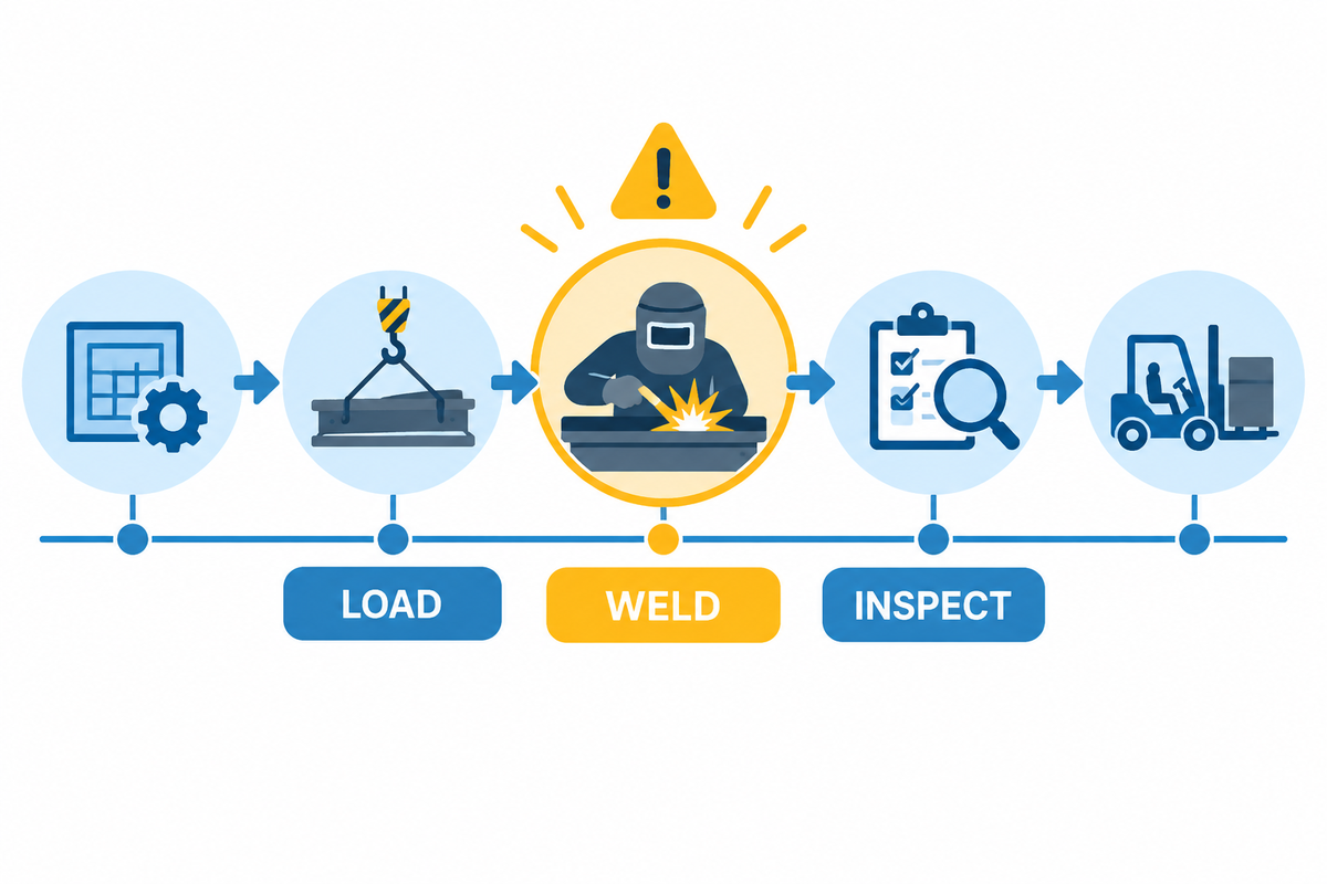
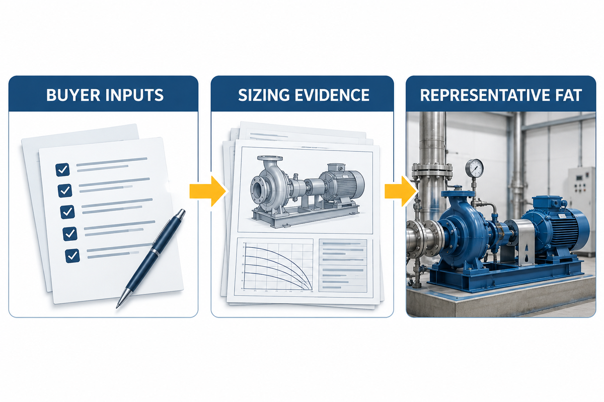
Manual loading at a second station can be covered, but it will not eliminate upstream and downstream constraints. Use the A3 positioner context as an input, then measure the buyer’s complete cycle before choosing station count. Map the entire cycle: Preparation, fixture loading, tacking, scanning, welding, cooling, inspection, unloading, rework, and changeover.
| Cycle element | Measured time | Can overlap robot welding? | Failure mode if ignored |
|---|---|---|---|
| Part preparation and fit-up | Plant measurement | Often upstream | Robot waits or weld starts on poor fit-up |
| Loading and clamping | Plant measurement | Possible on a separated second station | Operator becomes the takt constraint |
| Scan and path correction | Program-dependent | Usually inside cell cycle | Quoted arc time understates real cycle |
| Arc-on welding | Procedure and seam map | Core robot activity | Heat or sequence limits dominate |
| Cooling and inspection | Acceptance-dependent | Sometimes offline | Completed parts queue at QA |
| Unloading and changeover | Plant measurement | Architecture-dependent | Station change does not improve throughput |
| Consumable replenishment | Shift observation | Sometimes | Stops interrupt the apparent automated welding cycle |
| Fault recovery | Representative challenge | No | Average output hides long recovery events |
| Material staging | Plant measurement | Usually upstream | Industrial automation waits for parts |
For finance compare good parts per staffed hour – not theoretical rotation speed. For the plant manager, identify which task sets takt after automation. For QA, include inspection and rework. For procurement, have suppliers quote the same cycle boundary to ensure proposals remain comparable.
The right positioner cannot correct a weak welding and assembly flow. Track how operators load and unload each station, how setup changes with the variety of welding jobs, and whether manual welding or preparation is the hidden constraint. Consistent welding results depend on controlled inputs and acceptance, not on positioner speed alone.
Run a Cell-Level Safety and Intervention Review
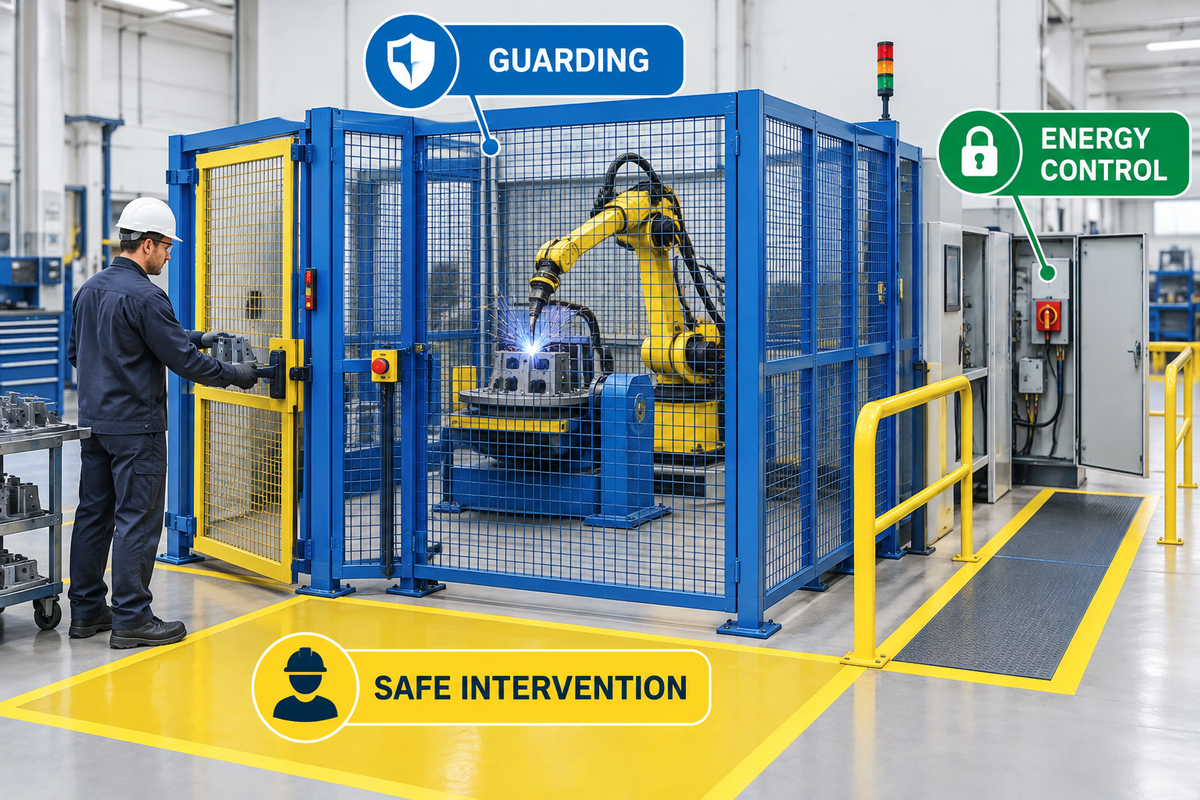
OSHA’s robotics standards page refers users to relevant machine guarding, hazardous-energy control, and electrical, and related standards. A robot-positioner cell also includes arc radiation, fumes and spatter, hot workpieces, pinch and crush zones, stored energy, and loading access. The risk assessment needs to consider the entire application and its lifecycle, and not just the robot arm.
The AWS D16 committee work on robotic and automatic welding is focused on the development of standards and guides. Use the latest editions of the relevant standards, and qualified safety personnel for the target jurisdiction and cell design.
The official ISO catalogue entry for ISO 10218-1:2025 provides the current publication reference for industrial robot safety requirements. Use the relevant complete standards; catalogs, pages or this article are not substitutes.
Safety boundary: this article is a procurement and engineering-planning guide. It is not a risk assessment, standards interpretation, safety validation, or authorization to operate. Confirm current requirements and validate the installed system under its actual modes and tasks.
Issue an RFQ That Suppliers Can Size Correctly
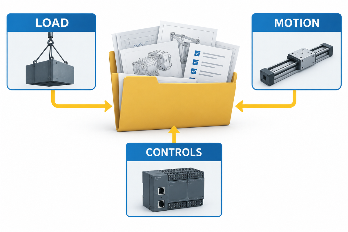
An effective RFQ requires the supplier to articulate assumptions rather than obfuscate them with a model number. The first-party configuration page is a starting point, not a substitute for project-specific sizing evidence. The workpiece family, CAD files, weld map, fixture concept, load worksheet, process requirements, cycle boundary, plant layout, utilities, controller preference, safety responsibility matrix and acceptance-criteria documentation are all useful RFQ inputs.
| RFQ category | Buyer supplies | Supplier returns |
|---|---|---|
| Application envelope | Representative and worst-case parts | Included/excluded part-family statement |
| Load and motion | Mass, CG, inertia inputs, weld-path mode | Sizing calculation and load-envelope confirmation |
| Reach and layout | CAD, access, floor and loading constraints | Simulation, signed layout, interference assumptions |
| Controls | Plant standard, network, data and recovery needs | Axis ownership, interfaces, safe states, backups |
| Process | Welding process, procedure constraints, inspection | Proposed equipment and qualification boundary |
| Cycle | Comparable start/stop boundary and product mix | Timed sequence with assumptions and exclusions |
| Acceptance | Pass criteria and representative test pieces | FAT/SAT plan, records, deviations, handover list |
Normally, quoted values must be marked as confirmed, calculated, assumed, optional or open. This normalization step prevents a lower quote from winning based on the absence of work critical to integration.
Witness a Representative Factory Acceptance Test
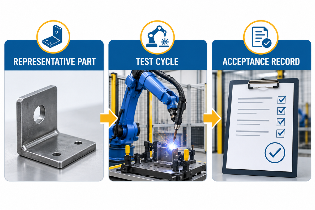
A FAT should reproduce the operating envelope as closely as possible. NIST’s robot-tolerance research supports keeping test conditions and uncertainty visible when performance is evaluated. A promotional video of free rotation of a load does not evidence that the complete robot path, controller, fixture and recovery logic meet your requirement.
Representative FAT witness sheet
- Identify the part, fixture, tool, program, software and drawing revisions that were tested.
- Verify load mass, center-of-gravity (CG) assumptions, mounting, and differences from production hardware.
- Run the hardest coordinated or indexed path at the declared speed and duty.
- Verify torch posture and clearance, check cable behavior and grounding, and review the weld result.
- Challenge a normal stop, emergency stop, and servo fault. Perform a restart and recovery as appropriate.
- Document cycle boundaries and results, deviations, owners, due dates, and retest requirements.
- Export backups, calibration/mastering records, manuals, training records, evidence of open-items, and other records not covered by the FAT.
State what the FAT does not prove. A factory acceptance test may not reproduce conditions at the buyer’s site, including the floor, extraction, upstream variation, utilities, operator practice, and long-term duty. Site acceptance and production release should close the gaps.
At the installed site, repeat the checks impacted by foundations, utilities, machine interfaces, network and safety integration, extraction, environmental conditions and operator tasks. Separately define SAT records from FAT records to ensure that a successful factory demonstration does not result in mistakenly taking delivery of robotic welding cell.
Avoid the Selection Errors That Create Expensive Rework
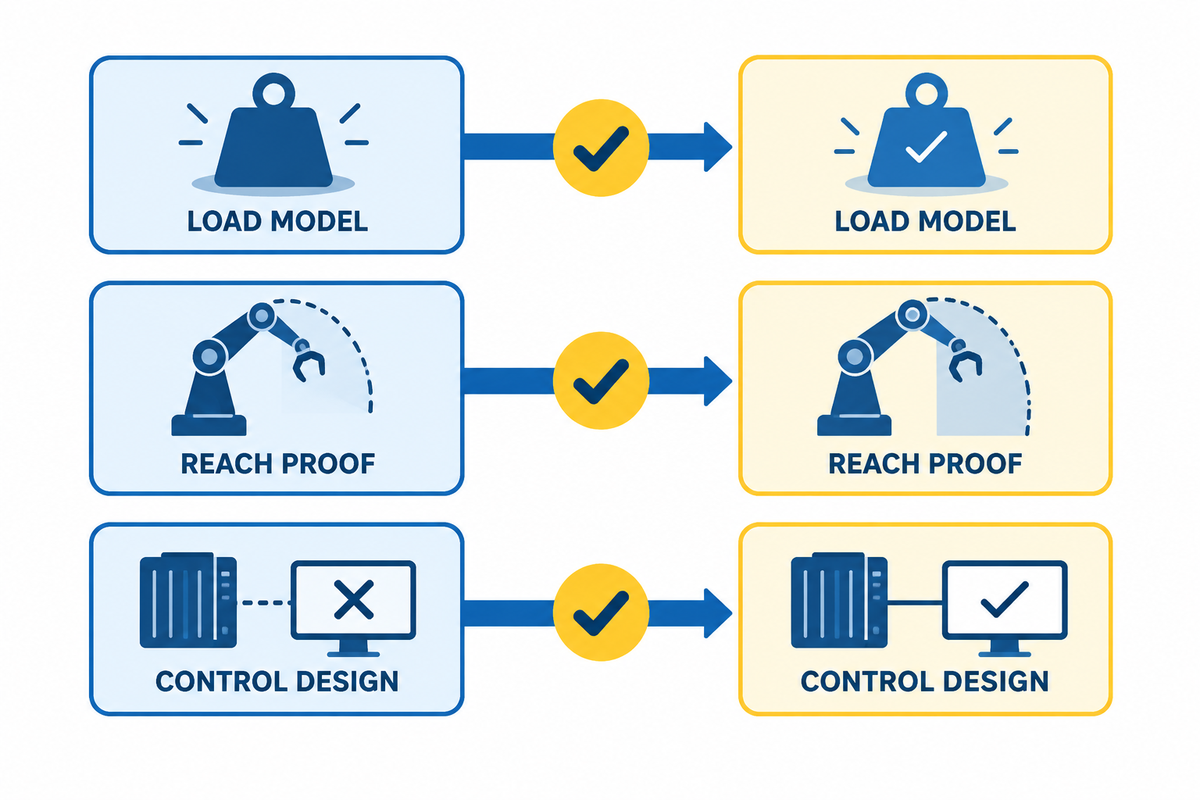
The A3 positioner-selection overview provides an independent reference for matching the workpiece, motion and cell-integration requirements behind these checks.
- Buying by kilograms alone: ignores CG, moment, inertia, acceleration, and duty.
- Testing the easiest part: leaves the worst reach, offset, and torch access cases unproven.
- Confusing rotation with coordination: overlooks controller ownership and interpolation.
- Treating fixtures as accessories: disconnects datums, grounding and program identity.
- Quoting arc time as cycle time: conceals scanning, loading, cooling, inspection and rework.
- Accepting an ambiguous axis count: creates discord among sales literature, layout and controller configuration. A signed kinematic diagram is requested.
- Using FAT as a universal guarantee: extends results to un-tested load, path and environment.
Frequently Asked Questions
What payload should a robotic welding positioner have?
Consider moment, inertia, load and eccentricity. Only consider mass (payload) once all the other moving components (workpieces and fixtures) and anything else that moves have been accounted for. Locate the combined CG and check supplier’s limits at that offset. An on-axis, catalog payload is not sufficient evidence to support an eccentric production assembly.
Can the positioner rotate while the robot welds?
Yes, if the system is designed and configured for coordinated external axis motion. The robot controller needs to know the axis position and interpret robot and positioner motion through the weld path. Verify servo and encoder integration, coordinate calibration, velocity behavior, safe states, cable routing, restart behavior, and a representative weld test case. A standalone unit that rotates on command may support indexing without supporting coordinated welding.
Is a single-axis rotary positioner enough?
A single-axis positioner is sufficient if rotating the part brings the required seams within reach of the torch in the validated load position while maintaining suitable welding postures. Longer parts may require headstock-tailstock support, and overlap in the loading may warrant two stations. Choose the simplest solution after a reach and path analysis. Don’t select the architecture based on the number of axes in competing quotations.
How is a welding positioner coordinated with the robot controller?
The positioner is designed as an external servo axis or connected through a defined indexed motion interface. The integration must define the drive and encoder, coordinate frame, calibration or mastering, motion commands, safety, faults, and protection. The emphasis and level of detail depend on the robot and controller in use, so a written integration design is not sufficient and a working example is required.
What information should be sent to a supplier?
Send your worst-case representative part CAD, dimensions, combined moving mass, CG, fixture concept, joint and weld map, required orientations, process and procedure constraints, production mix, cycle boundary, plant layout, load / unload method, utilities, control standards, safety responsibility boundary, inspection criteria, expected FAT/SAT records. Indicate uncertainty by marking or otherwise communicating it to the supplier, who may otherwise make assumptions and/or estimate the size of the uncertainty.
Which safety standards apply to a robot-positioner welding cell?
Answers vary by jurisdiction, cell design, robot application, welding process, and the employer’s obligations. Review the current robot-system, machine-guarding, electrical, hazardous energy, ventilation and welding safety requirements and standards. OSHA and AWS are good resources in the U.S. A web guide cannot determine compliance and cannot replace a qualitative risk assessment.
Move From Worksheet to a Reviewable Cell Concept
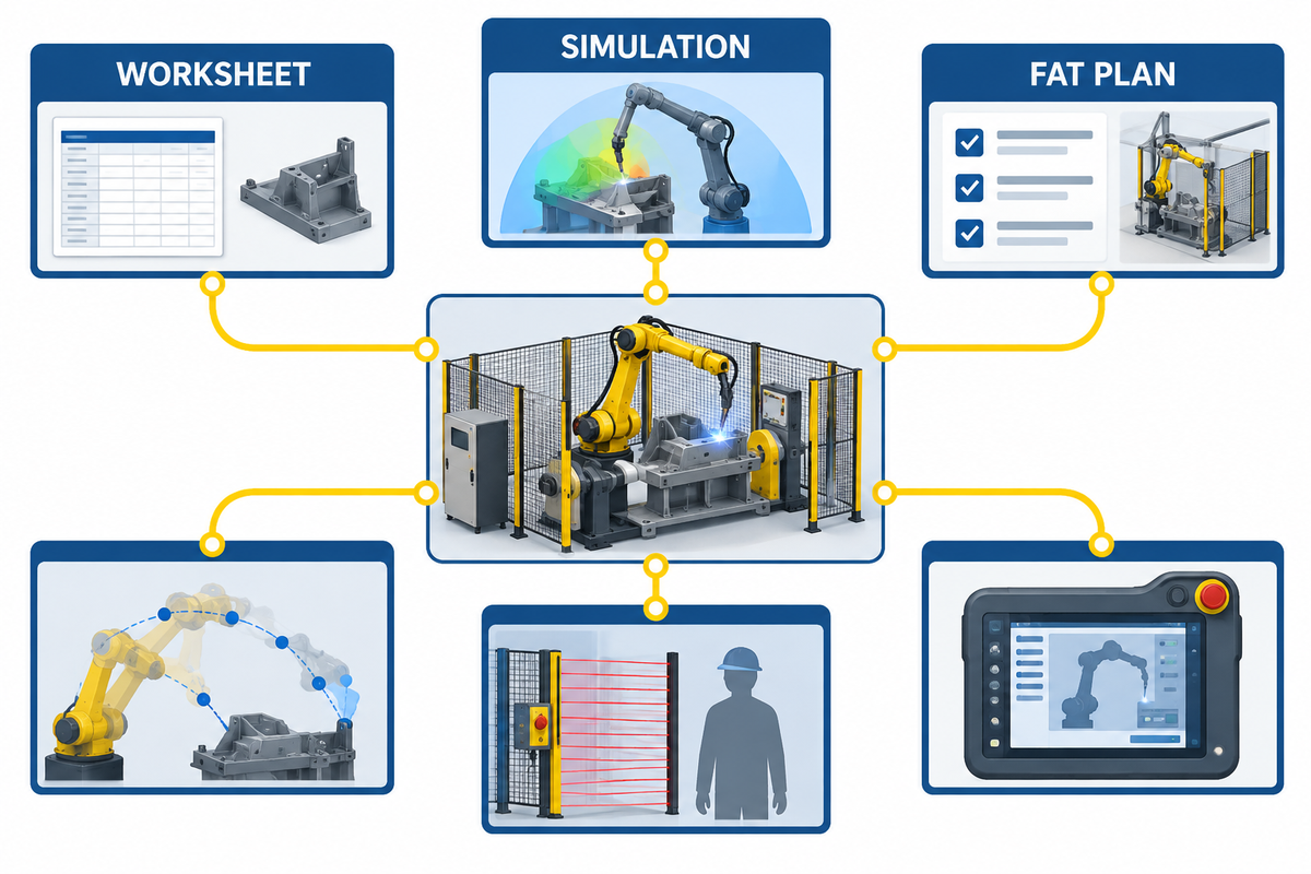
When your part-family table, load worksheet, weld map, cycle boundary, and acceptance criteria are ready, compare them with Zhouxiang’s cantilever welding robot configurations. Ask the engineering team to return a signed kinematic layout, explicit sizing assumptions, interface definition, and representative FAT plan. Learn more about Zhouxiang’s welding automation capabilities before starting a project review.
References & Sources
- OSHA — Robotics standards and related requirements
- American Welding Society D16 Committee on Robotic and Automatic Welding
- Association for Advancing Automation — positioner selection context
- NIST — tolerances and uncertainty in robotic systems
- NIST — calibration and registration tools
- ISO — ISO 10218-1:2025 catalogue entry
- Zhouxiang – cantilever welding robot product page (first-party configuration source)
- Zhouxiang — company profile (first-party brand source)
Equations and worksheets in this guide are planning aids. Final sizing of equipment and welding procedures and acceptance criteria require project-specific engineering and the most current and applicable documentation.