Get in Touch with Zhouxiang

Weld Inspection: NDT Methods, Defect Types & Standards [2026]
![Weld Inspection: NDT Methods, Defect Types & Standards [2026]](https://zxweldingrobot.com/wp-content/uploads/2026/05/0-6.webp)
Contents
show
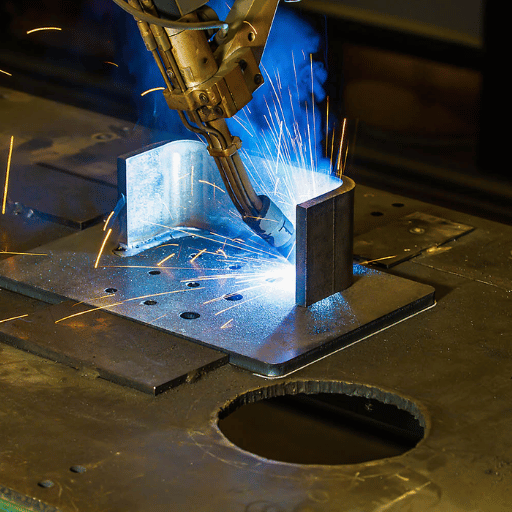
Each structural weld has a load calculation. That load calculation assumes a good joint – one without cracks, unconsolidated regions and porosity that can cause fatigue failure under cyclic loading. It is the weld inspection that allows engineers to verify that assumption.
This reference details the entire inspection process: the eight defect types inspectors look for, all six leading NDT techniques with recommendations for which is right for your joint type, present AWS D1.1 and ISO 5817 acceptance criteria, a repeatable three-phase inspection checklist, and the impact automated robotic welding cells have on the pass-rate equation on structural steel projects.
Quick Reference — Weld Inspection
| Primary standard (structural steel) | AWS D1.1/D1.1M:2025 (25th edition, March 2025) |
|---|---|
| International fusion weld standard | ISO 5817:2023 — Quality Levels B (highest), C, D |
| Pre-weld checks | Joint fit-up, bevel angle, root gap, WPS review, consumables verification |
| In-process (interpass) | Preheat coverage, bead geometry, slag removal, interpass temperature |
| Post-weld (final) | VT first, then NDT method per loading condition and code requirement |
| Qualified inspector credential | CWI (AWS), Level II NDT per ASNT SNT-TC-1A, or ISO 9712 (third-party) |
| AWS D1.1 undercut limit (static load) | Accumulated length with depth >1/16 in ≤ weld length × 0.16 |
What Is Weld Inspection? Definition, Purpose, and Industry Scope
Weld inspection is the process to examine the welds to ensure they meet the dimensional, mechanical and the criteria called up in the relevant codes. It is the activities carried out prior to the welding, during weld sequencs and after the completion of a joint. It also applies on any structure where the fail of welds is having safety, authorities or structure implications, for example – building columns and bridge girders, pressure vessels, pipeline joints or shipbuilding.
The ultimate goal is not to discover failures after they occur, but to prevent every one of them. When properly performed, the pre-weld inspection identifies fit-up issues that make sound welds infeasible. In-process checks catch faults at the bead level, where repair is still possible without complete weld removal.
Post-weld inspection compares the completed welds and verifies the conformal compliance of each weld to the acceptance standards specified in the relevant code – AWS D 1. 1 in U.S. structural steel projects, ISO 5817 during International project or ASME Section IX and XIII condition appropriate equipment..
Inspection is a lot different than welder qualification inspection in one major way however, a CWI uses code criteria, not engineering judgment. Every time a weld has a discontinuity over the written limit, then it is rejected, no matter what the fabricator thinks about real risk in the structure. This sort of separation is precisely why third-party inspection is so reliable.
Learn more about how robotic welding technology addresses quality control at the process level before inspection begins.
Engineering Note — Destructive vs. Non-Destructive Testing
NDT (Non destructive testing) or NDE (Non destructive examination)—assessed weld without taking apart, cutting,breaking off or modifying the joint. DT ( destructive test)- Tensile, bend and macro-etch specimens—identification of mechanical parameters on qualification samples. DT consumes the joint.
In production NDT is the main tool, DT is for WPS and for welder’s qualification.
8 Common Weld Defects and How Inspectors Identify Them
Familiarity with what to inspect for is the most basic principle of weld inspection. These eight types of defects will be found to make up most rejections for structural, pressure vessel and pipeline works. Analysis of ship fabrication data has shown that cavities-porosity and blow holes-made up 44-58% of all defects in FCAW work; solid inclusions made up a further 25-37%.
A significant finding: 90% of ALL weld defectives are in fillet rather than groove butt welds – 75% of all defectives are in root runs. Inspection plans that allocate resource primarily to fillet root passes will catch the majority of production defects before they reach final QC.
| Defect Type | How to Identify (VT) | AWS D1.1 / ISO 5817 Limit | Primary NDT Method |
|---|---|---|---|
| Cracks | Fine linear marks at weld surface or heat-affected zone; may need 10× magnification | Zero tolerance — all cracks reject under AWS D1.1 and ISO 5817 at all quality levels | VT (surface), UT or RT (internal) |
| Porosity | Round pits or visible blow holes on bead surface; internal pores not visible to VT | AWS D1.1: sum of piping porosity diameters ≤ 3/8 in per linear inch of weld (cyclic loading, Table 8.2). ISO 5817 Level B: ≤1% cross-section area | VT (surface), RT or UT (internal) |
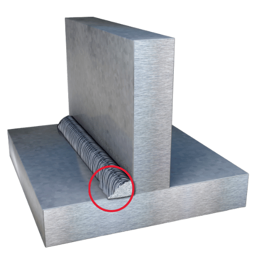
| Undercut | Groove or notch along weld toe; reduces base metal cross-section | AWS D1.1: depth >1/16 in — total accumulated length ≤ weld length × 0.16. ISO 5817 Level B (t >3mm): depth ≤ 0.05t, max 0.5 mm | VT (with weld gauge) |
| Lack of Fusion (LoF) | Not visible to VT; appears as lack of bond at fusion line | Not permitted under ISO 5817 at all levels (B, C, D); AWS D1.1 Clause 8.9 prohibits all lack of fusion | UT, RT (limited for planar defects) |
| Incomplete Penetration | Unfilled root; visible as a linear dark line on RT film | Not permitted in CJP groove welds (AWS D1.1); ISO 5817 Level D only: h ≤ 0.2t max 2 mm — not permitted at Level C or B | RT, UT |
| Slag Inclusions | Non-metallic deposits; dark streaks or spots on RT film | ISO 5817 Level B: h ≤ 0.2s max 2 mm, length ≤ s max 25 mm. Level D: h ≤ 0.4s max 4 mm, length ≤ s max 75 mm | RT (primary), UT |
| Arc Strikes | Localized hardened or discolored spots outside weld boundary | Not permitted — AWS D1.1 Clause 8.9.5; ISO 5817: not permitted at Level C or B (Level D: permitted only if base metal properties unaffected) | VT, MT |
| Overlap / Cold Lap | Weld metal extends past the toe without fusing to base metal; common in GMAW | Not permitted per AWS D1.1 visual acceptance criteria | VT |
Inspector Note — Where Defects Concentrate
In progressive structural steel work, spend inspection resources on fillet weld root passes first. Comparative analysis of offshore and shipbuilding fabrication data on NDT interrogation consistently demonstrates that in the reported data, approximately 75% of all weld defect types occur in root runs. Multi-pass heavy plate applications of GMAW and FCAW require obligatory interpass examination subsequent to each root and first fill pass.
6 NDT Methods for Weld Inspection — When to Use Each
Sometimes selecting the right NDT technique is overlooked when planning an inspection. RT remains the dominant technique in some fabrication sectors – accounting for 90% of NDT in shipyard applications – yet RT offers great difficulty in identifying planar defects including cracks and lack of fusion. Understanding each technique’s capability boundaries is the starting point for any sound inspection plan.
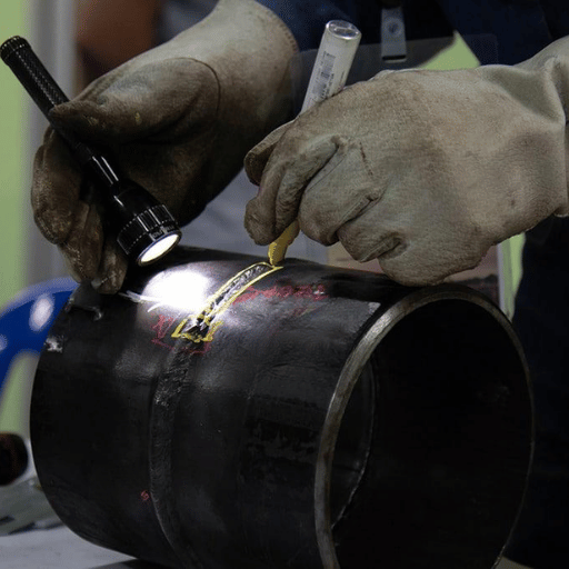
Visual Testing (VT): The First and Most Fundamental Check
Visual inspection is an essential first step in every weld assessment. AWS D1.1 Clause 8.9 mandates that all production welds are initially evaluated visually before other examination procedure is performed. VT has none of the personal exposure hazards of radiation, electric couplant, or toxic fumes and minimal artifice (a weld gauge set, a straight edge, and good illumination). For surface-accessible defects (undercut angle and depth, weld profile, arc strikes, overlap), VT can be effective. For subsurface or volumetric determinations additional NDT is needed.
Probability of detection (POD) for surface cracks, visual examination: 70-80% for 30-37 mm macrocracks in accessible positions; to reach 90% POD need bricks in the wall > 160 mm – sub-millimeter features and diffraction-quality surface cracks remain undetected.
Equipment: Fillet weld gauge set, undercut depth gauges, straight edge, 1.75minimum magnification as per AWS D1.1, sufficient illumination (500 lux as per AWS D1.1 Annex J).
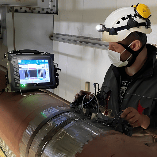
Ultrasonic Testing (UT) and Phased Array PAUT
Ultrasonic testing results from transmission of high-frequency mechanical waves through the weld. Discontinuities deflect the waves which when received by the transducer, enable transit time calculations to identify flaw location and depth. UT is the most common method for internal shop weld flaws in structural steel – lack of fusion, incomplete penetration, and cracks are easily located in walls thicker than 8 mm.
A well-known time-of-flight diffraction limitation of typical manual UT is operator inconsistency. Myriad testing a dozen identical carbon steel weld specimens with a dozen different operators gave a range of 41.7% to 100% POD for similar flaws – an average POD of only 57.4%. Consequently, an ordinary UT operator misses about 4 out of 10 penetrations.
Phased array ultrasonic testing (PAUT) overcomes this limitation by electronically “steering” the beam to multiple angles in a single pass over the weld. Where conventional UT must make 8 passes with 2 angle probes, PAUT can make the same number of passes with one probe – with data acquisition rated LOW versus HIGH for conventional UT. In direct comparison testing of PAUT and manual UT on carbon steel butt welds, PAUT achieved 100% POD against 57.4% average for manual UT.
One key PAUT limitation: transverse (fatigue) cracks are not reliably detected in standard single-line scan mode. High fatigue crack potential applications (bridge structures, crane runway rails) should test PAUT in conjunction with Time-Of-Flight Diffraction (TOFD), which can detect transverse flaws that PAUT misses. Combining PAUT with TOFD is now considered best practice for structural steel inspection.
Zhouxiang’s automated welding system makes UT the primary post-weld testing method used. High inspection rates (97% versus 82% pass rate) result from use of robotic welding cells for a bridge steel fabricator in China. This results from tighter heat input control and full weld parameter traceability available with automation. More on this in the Automated Inspection section below.
Radiographic Testing (RT): X-Ray and Gamma Ray
Radiography, employing either X or gamma rays, images the interior of the weld to reveal flaws such as porosity, slag, and incomplete penetration. RT is suitable for logging three dimensional picture of internal volumetric flaws and can record images. It is specified in several pressure vessel and pipeline standards (ASME VIII, API 1104) when volumetric testing is indicated.
RT achieved a 93.3% POD (28 of 30 defect specimens detected) in rounds of blind testing. RT shoots a single 2D image of the weld interior. It cannot reliably detect planar flaws such as missed fusion or cracks which are oriented parallel to the inspection beam. RT as the only NDT method on welds with primary planar flaw risk reveals a capability gap. Radiation zone requirements, film handling, and processing add cost and scheduling complexity that UT-based methods avoid.
Magnetic Particle Testing (MT)
Magnetic particle inspection involves applying a magnetic field to a ferromagnetic base metal (such as steel or titanium alloys). Adherent iron particles are attracted to the surface and near surface discontinuities that cause flux leakage. MT can find flaws as small as 0.1 mm wide near the surface; penetrating several mm will depend on flux strength and particle type.
MT cannot be used on austenitic stainless steel, aluminum, titanium, or other nonferromagnetic metals. Liquid Penetrant (PT) or Eddy Current (ET) testing is employed instead. AWS D1.1 clause 8.10 allows MT to be used on various connections where the standard calls for surface examination.
Liquid Penetrant Testing (PT)
Liquid Penetrant Testing identifies surface breaking flaws due to capillary actions; a penetrant is placed on the then cleaned weld, left to penitrate, then removed leaving any remaining indication to be drawn to the surface by a developer; creating a visible cue. Liquid penetrant testing can be used on any non-porous surface material: steel, aluminum, titanium, ceramics, glass, etc.. making it the surface examination method of choice on non-magnetic material where magnetic testing is not applicable.
limitation: PT only reveals defects to the surface. It will not be able to detect any subsurface anomalies. Regarding weld inspection it is used in addition to VT, as hairline cracks near the surface aren’t always visible to the naked eye.
And is common place in the aerospace and chemical process fields, and as an alternative practice for structural steel structures when MT isn’t applicable.
Eddy Current Testing (ET)
Eddy current testing uses a probe coil to induce a time varying magnetic field in a conducting material, which reacts with the material to create a circulating eddy current. Any flaw in the material alters the eddy current pattern, changing coil impedance in a measurable way. ET can scan quickly over a conducting surface with no couplant and is sensitive to cracks on or near the surface through coatings.
ET is used in weld inspection for post- weld surface crack detection in heat exchangers, tube welds and aerospace structures. Its use for inspection of structural steel welds is not as widespread as UT or MT however due to its greater speed and contactless operation, it is more suitable for high speed automated surface scanning during production.
NDT Method Selection Matrix — Structural Steel Joints
Reference of using this matrix as initial point. Always Confirm with the applicable code requirement for your own project and loading condition.
| Joint Type / Condition | Primary Defect Risk | Base Metal Thickness | Recommended NDT | Backup / Supplement |
|---|---|---|---|---|
| T-joint (fillet) | Lack of fusion at root, porosity | <12 mm | VT + MT | UT if code-required |
| Groove butt (structural) | Incomplete penetration, cracks | 12–25 mm | Conventional UT | RT if UT not feasible |
| Groove butt (heavy plate) | Hot cracking, multi-pass LoF | >25 mm | PAUT + VT | TOFD for transverse cracks |
| Bridge / cyclic-load structure | Fatigue cracking, lack of fusion | 20–40 mm | PAUT + TOFD | MT (surface supplement) |
| Non-ferromagnetic weld (Al, Ti, austenitic SS) | Surface cracks, porosity | Any | PT + VT | ET for conductive surfaces |
| High-volume production | All defect types, process drift | Any | Automated machine vision / in-process PAUT | VT + MT on statistical sample |
Weld Inspection Standards: AWS D1.1, ISO 5817, and ISO 3834

There are three standards that are followed for most structural and industrial weld inspection globally. You must know the standard that applies to your project—and what the acceptance standards require—before starting any inspection. An incorrect standard used, or an old edition is used will result in non-conforming work—even if the welds are sound physically.
| Standard | Current Edition | Scope | Key Acceptance Criteria | Typical Application |
|---|---|---|---|---|
| AWS D1.1/D1.1M:2025 | 25th edition, ANSI-approved March 19, 2025 | Carbon and low-alloy constructional steel; structural welding for buildings, bridges, and general structures | Table 8.1 (static load), 8.2 (cyclic tension), 8.3 (cyclic compression). Cracks: zero tolerance. Undercut: depth >1/16 in, accumulated length ≤ weld length × 0.16. Piping porosity: sum of diameters ≤ 3/8 in per linear inch | US structural steel construction, bridge fabrication, building codes (IBC) |
| ISO 5817:2023 | Fourth edition, February 2023 | All fusion-welded joints; steel, nickel, titanium; thickness ≥ 0.5 mm; SMAW, GMAW, GTAW, SAW, PAW | Three quality levels — B (highest), C, D. Undercut Level B (t >3mm): ≤0.05t max 0.5 mm. Porosity Level B: ≤1% cross-section. Cracks: not permitted at any level. Slag Level B: h ≤0.2s max 2 mm, l ≤s max 25 mm | International projects, EU structural steel, EN 1090 compliance, general industrial fabrication |
| ISO 3834 | ISO 3834-2:2021 (Part 2 — full requirements) | Quality requirements for fusion welding of metallic materials; covers the manufacturing process rather than acceptance criteria | Specifies what must be documented — WPS, PQR, welder qualifications, equipment maintenance, material traceability, NDT records — not dimensional limits | Supplier qualification for export manufacturing; EN 1090 structural requirement; aerospace and rail supply chains |
A brief note on the standard selection: AWS D1.1 and ISO 5817 are not interchangeable standards. AWS D1.1 defines a two level pass/fail system (action of the weld under static loads, or action of the weld under cyclic loads) with specified measurement limits. ISO 5817 defines three quality levels (B/C/D) that are mapped to application type what the specification contract specifies, for example: A ISO 5817 compliance clause (e.g., Level B) gives the most stringent acceptance criteria.
For projects with compliance to EN 1090 (European structural steel specification) a correlation of ISO 5817 stress levels to the execution class specified in the specification documents should be adopted.
According to Travis Green, PE, SE, CWI (Chair, AWS D1 Subcommittee D1Q) on the 2025 edition: “The D1 committees solicited input from users and other industry subject matter experts to substantially revise AWS D1.1/ D1.1M:2025.” The 2025 revision has piping porosity limits for cyclically loaded structures and reconsidered the acceptance of linear or rounded discontinuities of welded bridge and transportation structures. Learn how Zhouxiang implements AWS D1.1 welding compliance in its robotic welding cell designs.
Step-by-Step Weld Inspection Procedure: Three-Phase Checklist

How Do You Inspect a Weld Step by Step?
A proper weld inspection consists of three phases: pre-weld, in-process (interpass), and post-weld. There is a separate inspection point for each phase. Some structural fabricators commonly omit an in-process inspection on multi-pass heavy plate welds, allowing subsurface flaws to be thermally trapped between subsequent passes, thus increasing their cost of repair exponentially.
Phase 1 — Pre-Weld Inspection
- Check out WPS and PQR in the ISO tables – verify the welding procedure specification has been approved, qualified to the relevant standard, and is posted at the work station
- Check joint fit-up: measure root gap (compare to WPS tolerance), bevel angle, and joint alignment confirm groove geometry WPS
- Inspect base metal identification, check corresponding mill test certificates against material specification; look for indication of laminations, inclusions or damage of surface in the weld zone.
- Check consumables – filler metal classification, heat number and storage conditions (low hydrogen electrodes require controlled storage per AWS D1.1 Annex A)
- Check preheat compliance–take contact or IR temperature measurement; AWS D1.1:2025 requires preheat coverage at minimum 2 base metal thicknesses for material less than 1.5 in.
- Inspect for cleanliness, grinding or pickling away all mill scale, paint, moisture, contamination from weld area plus at least 25 mm on either side.
Phase 2 — In-Process (Interpass) Inspection
- Inspect root pass first before moving on – ensure root is fused, no lack of penetration, start stop defect, before laying the fill passes
- Check interpass temp- measure and record prior to each subsequent pass. The maximum interpass temperature specified in the WPS must not be exceeded. ( controls heat-affected zone ductility)
- Verify slag removal — confirm complete slag removal between passes; residual slag trapped between beads causes inclusions in subsequent passes
- Monitor bead geometry – bead width and convexity limits per WPS; too much convexity on a cap pass induces stress concentration at the weld toe.
- Interpass cracks- This occurs when the finished applications of a pass is checked over for potential longitudinal cracks or star cracks before a later pass is built up; such cracks are considerably cheaper to correct than those associated with buried defects
Phase 3 — Post-Weld Inspection
- Visual inspection (VT) – initial inspection, prior to NDT, AWS D1.1 Clause 8.9; inspect all available weld surfaces for cracks, undercut, overlaps, arc strikes, profile and dimensional accuracy;
- Choose NDT method- per joint type, applied standard and loading conditions (see NDT Selection Matrix provided above)
- 3.06 Apply NDT- adhere to the procedure standard (the recommended standard for the task -man level II as per ASNT SNT-TC-1A; AWS D1.1 Annex K in case of Ut; EN ISO 17640 for European projects).
- Acceptance criteria to be applied- assess all indications with relevant code(s) (AWS D1.1 Table 8.1/8.2/8.3 or ISO 5817 Level as per contractual requirement)
- Record results- weld map location, inspector qualification, NDT method applied indications, acceptance / rejection, inspector signature ; ISO 3834 asks: All weld map process , No inspection records must be , fully traceability.
- Disposition nonconformances 2- rejected welds to be documented for rework/repair AND re-inspected per original or more conservative method after re-work/repair
Common Mistake to Avoid
The ultimate test of a weld inspection procedure is the interpass. Multi-pass structural steel welds (especially T-joints with demanding heavy fillet requiremetns) mandatorily require coverage of the root and fill layers to be effective. Visual inspection of the finished weld detects the repairability of the defect — measured in shifts rather than minutes. See how digital twin traceability enables 100% parameter logging across every weld pass. A root pass defect is a one-shift repair, whereas the same defect visualized on RT after a final pass pass(es) is a multi-shift rework, or a rejected weldment.
How Automated Robotic Welding Reduces Weld Inspection Failures
Weld inspection failures in manual fabrication operations trace back to one root cause more than any other: process variability. Human welders operating within a production schedule vary heat input, travel speed, torch angle, and arc length over the course of a shift. That variability creates the conditions in which porosity, incomplete fusion, and undercut develop – defects that then require NDT detection and repair.
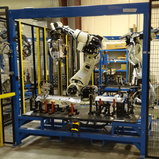
Robotic welding systems eliminate the principal sources of this variability by maintaining consistent travel speed, wire feed rate, and arc parameters across every weld, every shift, regardless of operator fatigue or skill variation. On NDT pass rates, that effect is measurable.
82%→97%
UT pass rate improvement after robotic welding installation at bridge steel fabricator, central China
FIRST-PARTY DATA — Zhouxiang Verified
80–85%
Arc-on duty cycle, robotic welding cell (vs. 25–35% for manual welding)
FIRST-PARTY DATA — Zhouxiang Verified
800→1,200 t
Monthly fabrication throughput increase with 3 robotic cells at Jiangsu steel structure fabricator
FIRST-PARTY DATA — Zhouxiang Verified
Three technical mechanisms drive the inspection improvement in robotic welding cells:
1. Consistent heat input. Arc-on duty cycle in a Zhouxiang robotic cell runs 80-85% versus 25-35% for manual welding. Higher, consistent arc-on time means more uniform heat input distribution – reducing the thermal gradients that cause porosity and hot cracking in structural steel joints.
2. Laser seam tracking with 3D vision. Laser tracking and 3D vision sensors in the system continuously monitor joint geometry and correct the weld path in real time. This adaptive capability compensates for workpiece fit-up variation – the condition that causes root gap inconsistency and incomplete penetration in manual welding on structural steel fabrication.
3. 100% weld traceability via digital twin. Every weld pass is recorded: voltage, current, travel speed, wire feed rate, torch position, and shielding gas flow – logged against the specific weld ID and joint location. This creates a complete inspection record before the NDT step, and allows engineers to correlate any NDT finding directly to the process parameters at that weld location. AWS D1.1 traceability requirements are met by design.
Reduce Your Weld Inspection Rejection Rate
Zhouxiang’s intelligent steel structure welding system combines laser seam tracking, 3D vision path correction, and full digital twin traceability. The documented result: UT pass rates from 82% to 97% on structural steel weld sequences that previously required extensive post-weld rework.
For fabricators evaluating the ROI case, see the robotic welding ROI calculation guide and the robotic vs. manual welding quality comparison.
The Future of Weld Inspection: AI, PAUT, and Digital Twin QC (2025–2026)
Four technology shifts are actively changing how weld inspection is performed at scale. Each addresses a specific limitation of conventional inspection practice.
1. PAUT replacing conventional UT as the new baseline structural steel NDT method. The market message rings loud and clear: phased array ultrasonic testing has a search volume of 720/month, with an upward trend line; conventional UT equipment is statistically flat. Performance data makes a compelling case: 100% POD for PAUT versus the 57.4% average for manual UT, combined with digital recordability that makes PAUT the clear choice for any inspection requiring documented results. PAUT+TOFD pairing is now normal for fatigue-critical structural welding in advanced fabrication facilities.
2. AI-enabled automated visual inspection. In-situ welded joint inspection systems paired with deep learning models detect welding-related arc phenomena such as bead geometry, surface porosity, and arc stability. Compared to conventional quality controls relying on sampling, the automated weld inspection system market is forecast to grow rapidly from USD 500 million in 2024 to USD 1.2 billion in 2033 (CAGR 10.5%).
3. Digital twin and weld traceability. Moving away from “document each final weld”, instead maintain data logs that relate arc voltage, amperage, travel speed, and thermal distributions to each weld ID# (digital twin). Integrating this continuous, full-envelope process data removes the black-and-white verdicts of conventional NDT (“pass” or “fail”) and enables predictive maintenance; out-of-tolerance process conditions during welding can be flagged before premature defect formation. See how digital twin weld data logging works in practice.
4. Whole process inspection, not just final weld inspection. Timing is the key operational difference: real-time welding monitoring systems use thermal cameras, process cameras, and arc parameter sensors to flag anomalies during the weld itself. The real-time weld monitoring system market size is projected to grow from USD 1.76 billion in 2025 to USD 4.14 billion in 2035 (CAGR 8.6%). Inline correction during welding is an order of magnitude more cost-effective than rework after the fact. See the guide to maintaining automated welding cell performance for operational details.
Q. “if the robot is accurate, you need less inspection.” in practice this is often false. Automated welding generally enables inspection to be performed on 100% of the production volume by delivering digital records that make traceable, reliable quality assurance attainable, more cost-effective, even practical.
FAQ — Weld Inspection
What qualifications does a weld inspector need?
For AWS D1.1 structural steel fabrication in the United States, the qualified signatory welder performing the welding obviously must be certified in accordance with AWS D1.1. The CWI performing the visual inspection from the American Welding Society is the normal qualification for NDT inspectors. NDT inspectors must hold ASNT Level II in the specific method employed (RT, UT, MT, etc.) according to SNT-TC-1A. For international projects and certification by a third-party inspection company the standard for NDT qualification is ISO 9712 certification NDE Level II. AWS D1.1:2025 defines these welding personnel qualification requirements in Clause 8.
How long does weld inspection take per joint?
The visual inspection of a completed fillet weld takes 5-15 minutes per weld, depending on the weld length and amount of weld access in the weld. Conventional UT on a groove butt weld joint is 20-45 minutes in duration, including set-up and documentation procedures, for a single- or multi-pass weld 12-25mm thick. PAUT on the same weld takes approximately half as long, due to fewer requisite scan passes. Film interpretation after the radiographic setup, exposure, and film processing takes 2-4 hours per weld minimum. The inspection method selection can significantly impact schedule on high-production fabrications.
What is the difference between destructive and non-destructive weld testing?
Nondestructive testing (NDT) is a measurement technique used to evaluate the weld non-invasively, without destroying or changing it – it is intrinsically a production-ready process. Destructive testing is used to assess mechanical properties; tensile, bend, nick-break, or macro-etch tests. Tensile and bend testing is performed on non-welded specimens, nickname break and macro-etch tests on welded specimens. Tensile and bend tests are necessary for WPS and welder qualification record documents (PQRs, WPQRs), not welds in production. They are both mandatory in a complete quality program per ISO 3834.
How often should welds be inspected on structural steel projects?
AWS D1.1 specifies visual inspection of all production welds. The value of NDT is determined by the Engineer of Record’s specification, type of joint, and load category. Cyclically loaded connections (highway bridges, bridge crane runways) generally require higher NDT sampling rates than statically loaded connections. Certain codes mandate 100% NDT for CJP groove welds in primary members. The inspection plan should be established in the project quality plan prior to production commencement, not in a production shop.
What does AWS D1.1:2025 require for visual weld inspection?
AWS D1.1 Clause 8.9 states that before any NDT testing, a weld must be accepted in visual inspection. Visual inspection checks for the following weld discontinuities: crack (zero tolerance), incomplete fusion (no allowance), undercut (permissible limit), overlap (no allowance), arc strikes (no allowance outside weld), porosity, and conformance to the weld size and weld profile dimensions of the WPS. The 2025 edition (25 th edition, March 2025) altered piping porosity limits and added clarifications to linear and rounded discontinuities.
Can robotic welding reduce my NDT inspection frequency?
A reduction in the NDT sampling rate is permissible in some codes and applications when the fabricator can supply a history of consistent, high-quality welds – a record usually generated by a robotic welding program combined with statistical process control. In a high-volume bid job with a lower NDT sampling rate, the average rejections for that NDT method will decrease, and the effect will be in cost and schedule. Zhouxiang’s bridge steel fabrication experience has seen a jump in UT pass rate from 82% to 97% after installation of a robotic welding station – active fabricator document.
About This Guide
This document was compiled using AWS D1.1/D1.1M:2025 (current March 2025 edition), ISO 5817:2023, and inspection performance data from peer-reviewed NDT research (ICWNDT 2018, University of Strathclyde structural weld analysis). NDT probability-of-detection data referenced for PAUT and manual UT are derived from laboratory controlled experiments—actual field use POD can result in a range of values that depend on joint geometry, access and inspector.
Zhouxiang’s weld quality improvement figures (82%→97% UT pass rate) are first-party data, documented as part of a definitive deployed solution at an industrial steel bridge fabricator in China, is especially noteworthy. Zhouxiang has been designing welding systems since 1991 and has 200+ documented patents to their name in robotic welding technology. This document outlines the specific inspection parameters that Zhouxiang’s automated welding systems address directly.