Свяжитесь с Чжоусяном

220 В/50 Гц против 480 В/60 Гц: соответствие сварочного робота энергосистеме вашей страны

Содержание
показывать
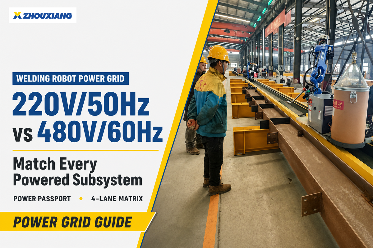
Welding robot voltage frequency compatibility is the verified match between the actual facility supply and every powered part of the cell.
Compatibility exists only when the actual supply matches every powered part of the welding cell and the facility network can support the combined installation. That is the practical meaning of welding robot voltage frequency compatibility.
Labels such as 480V/60Hz for the facility and 380V/50Hz for the cell may still lead to a compatible engineered design, but they cannot tell you which change is safe. Put the controller, welding power source, positioner, wire feeder, fume extraction, cooling equipment, service station, and control-panel auxiliaries on one electrical worksheet.
Five-question quick screen
- What voltage, frequency, phase, conductor arrangement and power-quality conditions are found at the relevant coupling point?
- What does each component nameplate and manual approve?
- Is the mismatch voltage, frequency, or both?
- Which loads overlap in the operating sequence, and what inrush do they create?
- Who will approve the final transformer, converter, protection, and commissioning plan?
This guide gives you a repeatable method to answer those questions before shipment. It is decision support, not a substitute for the cell manufacturer’s approval or a qualified electrical design.
The Short Answer: Match the Whole Cell, Not Just the Robot
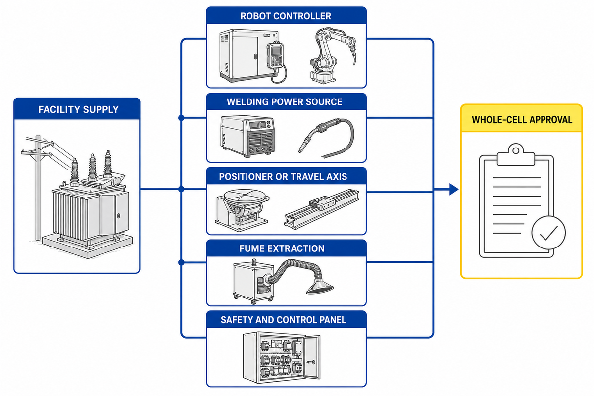
Think of a robotic welding cell as a small industrial power system with several loads, then place it inside the larger facility network. A wide-input welder doesn’t make a single-frequency fan compatible, and a complete component passport still can’t prove facility-level harmonic or transient acceptance by itself. That is why the pre-shipment worksheet must close the cell manufacturer’s unknowns before design approval.
This two-boundary view also matches the way current standards divide responsibility. ИСО 10218-2:2025 addresses industrial robot application and cell integration, while МЭК 60204-1 covers a machine’s electrical equipment from the point where the supply connects.
| Component class | What can differ | Document to check |
|---|---|---|
| Robot controller | Input range, phase, frequency, transformer option | Exact controller manual and order code |
| Источник питания сварки | Voltage taps, current draw, duty, 50/60Hz rating | Model specification and connection diagram |
| Wire feeder | Supply source, control interface, current and duty | Feeder manual and interconnect drawing |
| Positioner or travel axis | Motor/drive frequency, braking, inrush | Motor, drive, and axis documentation |
| Fume extraction | Fan motor voltage/frequency, starter or drive, airflow interlock | Extractor nameplate and motor/drive manual |
| Chiller or liquid cooling | Pump/fan ratings, phase, frequency, ambient limits | Cooling-unit data sheet and wiring diagram |
| Torch service station | Motor, solenoid, heater, air and control-voltage requirements | Service-station manual and I/O list |
| Safety and control panel | Control power, neutral, protective devices, SCCR | Single-line diagram, panel schedule and rating label |
| Vision and computing | Derived AC/DC supply, UPS, grounding and communications | Power-supply, UPS and network-device manuals |
| Service receptacles and lighting | Line-to-neutral voltage, neutral availability and protection | Panel schedule and destination-site rules |
Use a simple default: an undocumented rating is an unresolved point, not permission to connect. Ask the manufacturer or integrator to fill in each row in writing.
220V/50Hz vs 480V/60Hz: What Actually Changes?
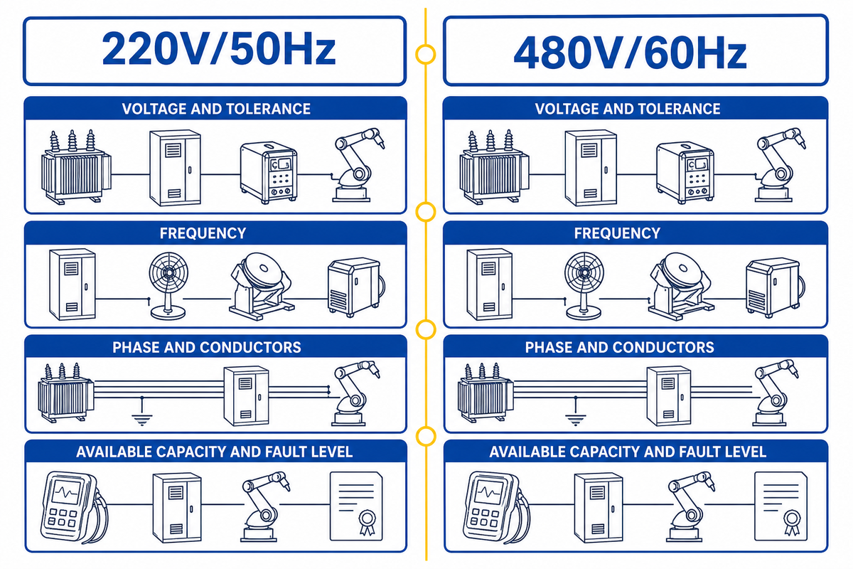
Voltage and frequency are separate compatibility questions. A transformer may solve some voltage differences, but a passive transformer cannot turn 50Hz into 60Hz. You also need to distinguish single-phase from three-phase service, and line-to-line from line-to-neutral voltage. A utility chart cannot prove that a three-phase 220V supply of adequate capacity exists beside the planned cell.
Voltage is the electrical potential; equipment must accept the actual line-to-line or line-to-neutral voltage at its terminals.
Frequency is the AC cycle rate; it can influence transformers, induction motors, fans, pumps, timing assumptions and magnetic components unless they’re specifically dual-rated.
IEC 60038 delivers standardized nominal voltage references, but those families are not an alternative for a site measurement and service record. Likewise, the US government’s Electric Current Worldwide reference cautions that industrial standards can vary from the domestic or commercial values listed for a country.
| Поле | Почему это важно | Who confirms it |
|---|---|---|
| Voltage and tolerance | Direct connection, tap, or conversion decision | Utility/site engineer and equipment manufacturer |
| Частота | Magnetic and motor-driven load suitability | Manufacturer documentation |
| Phase and conductors | Whether the intended connection is physically available | Qualified electrical designer |
| Available capacity and fault level | Transformer, protection, cable, and SCCR review | Facility electrical team |
Build a Grid-to-Arc Power Passport for Every Subsystem
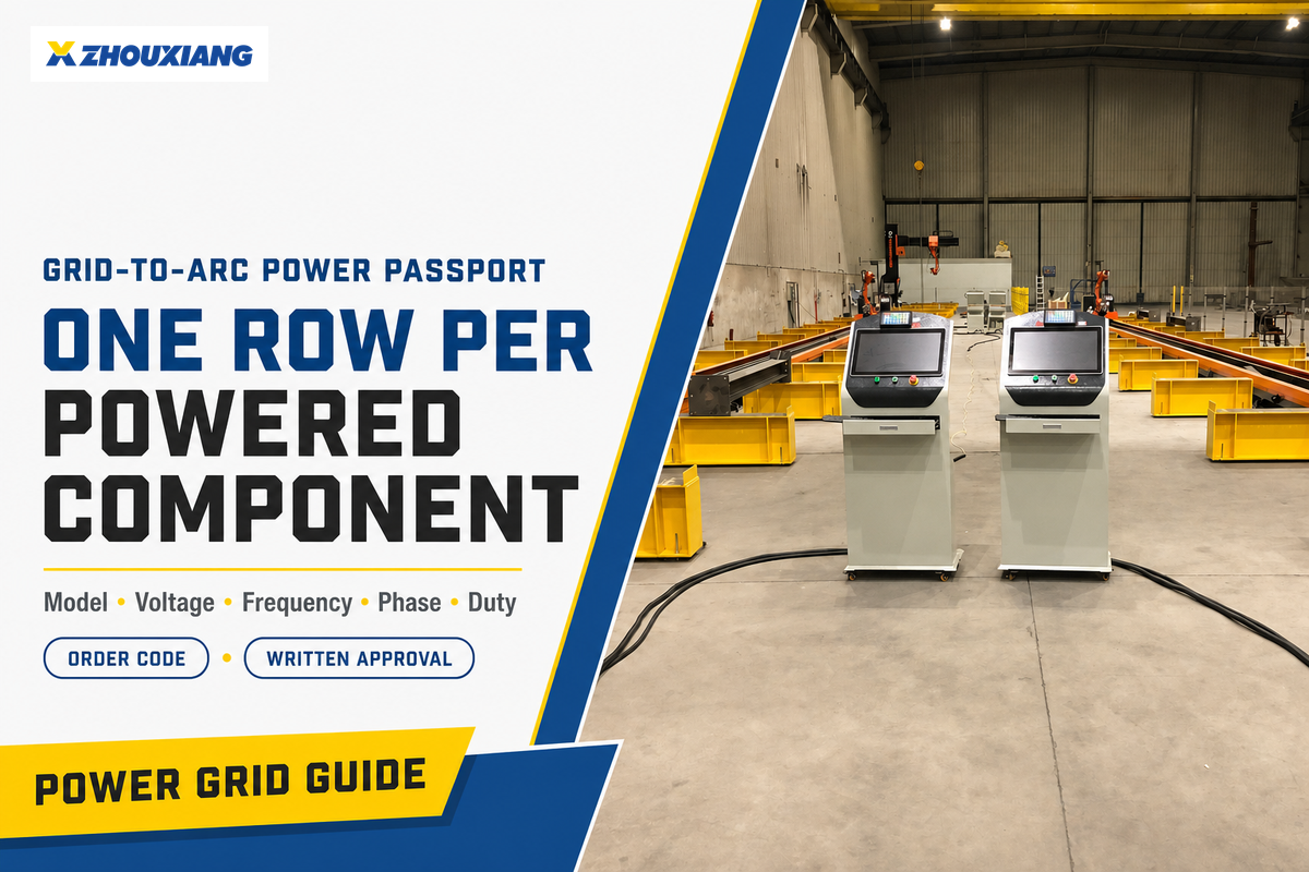
Grid-to-Arc Power Passport means one row per powered component, from the incoming disconnect to the welding arc. It prevents a salesperson’s “the robot is 480V-ready” from being mistaken for an approved cell design. Those country voltage families become only the starting data for this component-level record.
Чжоусян structural-steel welding robot solution illustrates why this matters: a project can combine robot motion, rail or cantilever travel, 3D vision, CAD/BIM control, workstations, and automatic torch-service functions. Only the quoted bill of materials determines which of those subsystems exist and which electrical rows you need.
Grid-to-Arc Power Passport fields
- Equipment tag, function, manufacturer, exact model, and order code
- Approved voltage range, frequency, phase, and conductor arrangement
- Full-load input current or kVA, power factor if relevant, and documented inrush
- Neutral and protective-earth requirements
- Approved taps, jumpers, settings, or external transformer
- Operating duty and which other loads can run simultaneously
- Decision, approving document, drawing reference, and responsible party
Identify the welding power source by exact model, not by brand family. For example, Miller’s Auto-Continuum 500 specification lists several three-phase input voltage families and 50/60Hz operation, while another model or option can have a narrower rating.
Apply the same rule to fans, extraction units, chillers, pumps, positioners, and control transformers. ABB’s motor guidance shows common 50Hz and 60Hz voltage families but directs users to the product catalogue for the exact motor rating, which is the correct evidence level for your passport.
Country Grid Families: Planning Examples, Not Installation Values
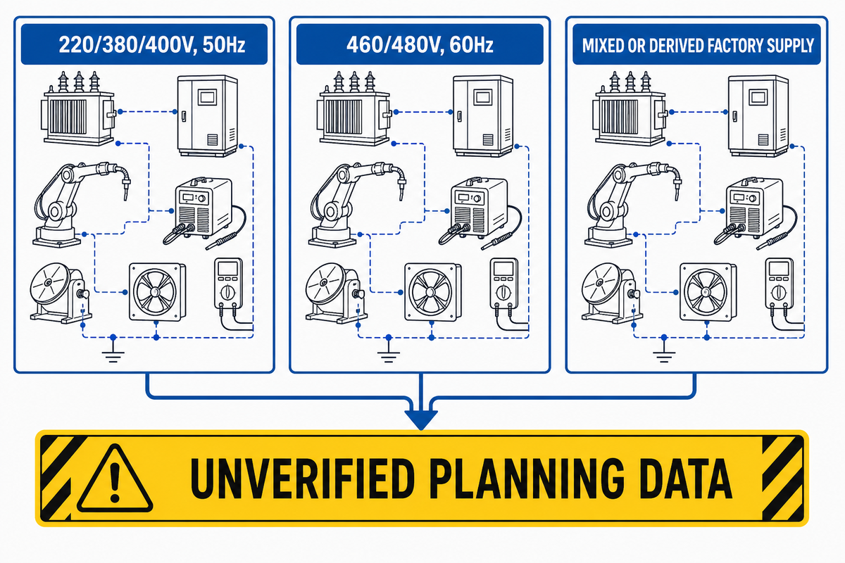
Use country voltage and frequency families to start a conversation, never to approve a connection. The useful question is not “What power does this country use?” but “What service will be available at this machine’s terminals?”
| Planning family | Typical screening concern | Proof still required |
|---|---|---|
| 220/380/400V, 50Hz | A 460/480V-only input or 60Hz-only auxiliary may not connect directly | Actual three-phase service, tolerance, grounding, capacity |
| 460/480V, 60Hz | A 380/400V or 50Hz-only load needs a documented disposition | Available voltage, frequency, neutral, fault level |
| Mixed or derived factory supply | An internal transformer may create a different local voltage but not a different frequency | Single-line diagram and point-of-connection measurement |
Legacy plants may have 480V distribution and an existing 400V transformer, while a new building in the same city may not. Dedicated generator supplies, weak grids, long feeders, and large neighboring loads can also change the quality of power seen by the cell.
Procurement rule: put measured or utility-confirmed facility values in the RFQ and label country-table values “unverified planning data.”
When a Transformer Is Enough, and When It Is Not
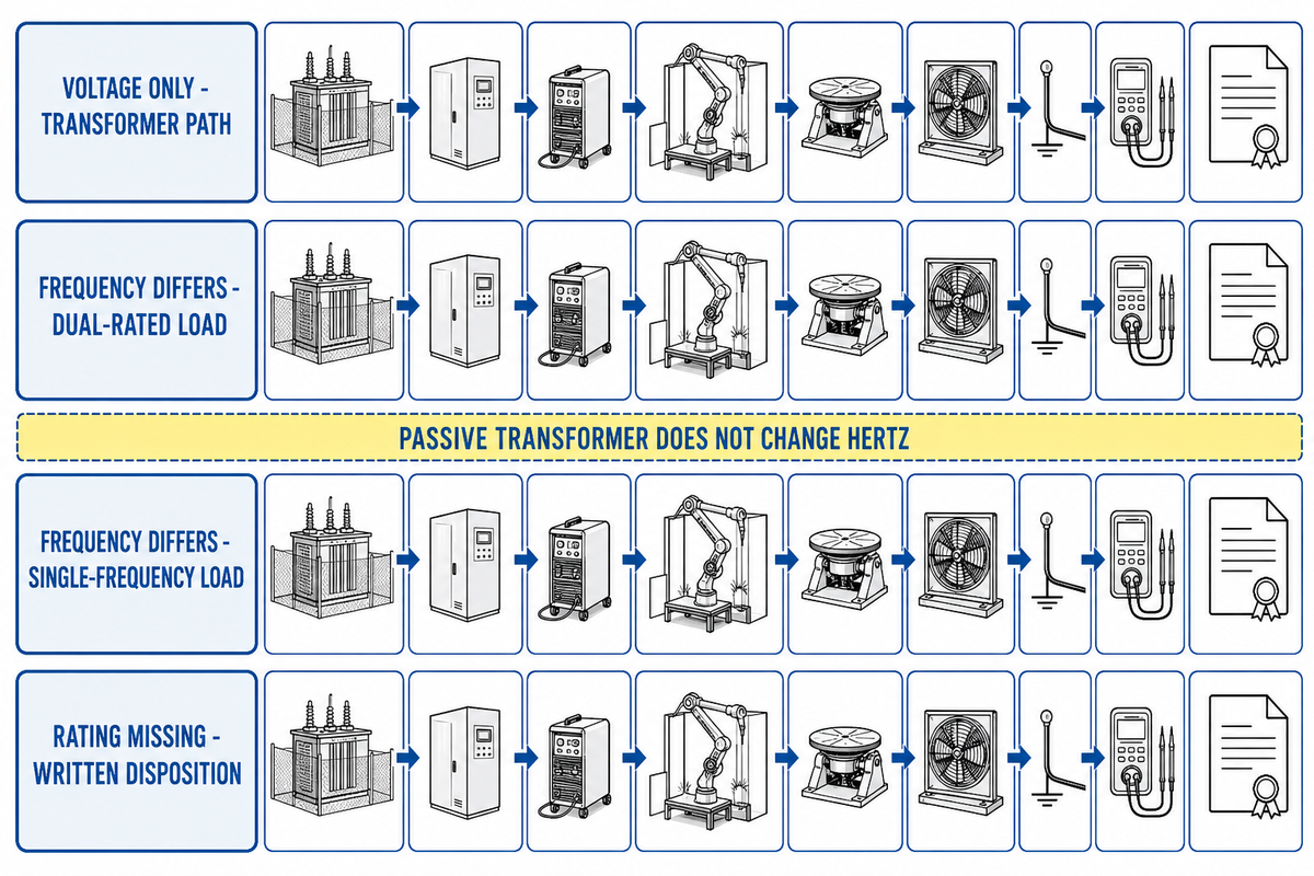
Transformers may solve a voltage mismatch only when every downstream load accepts the unchanged supply frequency. If the frequency itself is incompatible, you need an approved active solution, a compatible replacement, or a redesigned cell. The plant and feeder conditions from the country-grid check determine which path is available.
Schneider Electric’s transformer guidance is unambiguous: a passive transformer changes voltage, but its output frequency remains unchanged. Therefore, 60Hz-only equipment does not become 50Hz-compatible just because a transformer produces the right voltage.
| Observed mismatch | Likely path to evaluate | Do not assume |
|---|---|---|
| Voltage only; load is explicitly 50/60Hz | Direct reconfiguration or engineered transformer | Any convenient transformer ratio is acceptable |
| Frequency differs; load is explicitly dual-rated | Resolve voltage, then confirm all settings and derating | One dual-rated device qualifies all loads |
| Frequency differs; load is single-frequency | Replacement, approved active converter, or redesign | A passive transformer changes hertz |
| Rating is missing or ambiguous | Obtain exact manual and written manufacturer disposition | Silence means compatibility |
Be wary of universal derating advice. Schneider describes a voltage/frequency derating exception for certain transformer applications, but that example is product-specific and cannot be applied wholesale to robot controllers, drives, welding power sources, or auxiliaries.
Installing a transformer also changes the electrical-system boundary, not just the voltage. In covered US workplaces, OSHA 1910.304 shows why the secondary grounding arrangement and both line-to-line and conductor-to-ground voltage matter when selecting protection.
Transformer handoff: require the secondary conductor arrangement, grounding/bonding method, neutral treatment, disconnect, overcurrent protection, fault-duty basis, and breaker voltage rating on the released single-line diagram.
4-Lane Compatibility Matrix: Direct, Transformer, Replace, Re-engineer
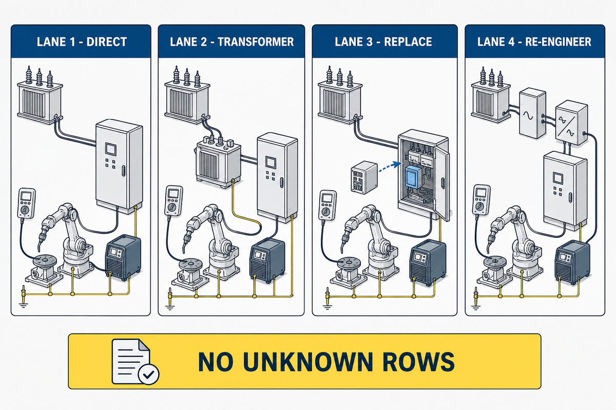
Give every Power Passport row one of four dispositions, and do not release the purchase until there are no “unknown” rows. This turns a vague compatibility discussion into a controlled engineering handoff. The transformer boundary from the preceding section is one of those four dispositions.
Lane 1: Direct
The exact model and configuration explicitly accept the measured supply.
Lane 2: Transformer
Voltage changes, frequency remains approved, and the transformer plus protection are engineered.
Lane 3: Replace
A mismatched component is swapped or factory-configured for the destination grid.
Lane 4: Re-engineer
Active frequency conversion, split supplies, or architecture changes need system approval.
Include the drawing or manual revision that supports each matrix decision. It is a procurement control, not a conformity certificate or permission for unqualified electrical work.
Between Lane 1 and Lane 2 sits a common trap: the welding power source accepts a broad range, so the team stops checking. Miller’s published automation specifications show why product-by-product review matters; even options presented within one automation system can have different input ranges.
How to Size the Electrical Interface Without Guessing
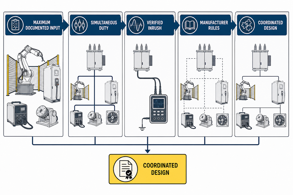
Start with a simultaneous load schedule, not a fixed spare-capacity percentage. Final transformer, converter, breaker, and conductor sizing belongs to a qualified designer using the selected equipment data and applicable code.
- Record the maximum documented input of each load.
- Mark continuous, intermittent, and non-simultaneous operation from the control sequence.
- Add verified motor starting, capacitor charging, transformer energization, and other inrush where applicable.
- Apply the selected transformer’s or converter’s manufacturer rules for efficiency, loading, ambient temperature, altitude, and harmonics.
- Check protection, conductors, voltage drop, fault duty, and the machine’s short-circuit rating as one coordinated design.
Hypothetical planning example, not a final design
Imagine that the passport shows 18kVA of loads that can run together, plus a separately documented 6kVA intermittent load that can overlap during torch service. Its planning schedule is 24kVA before efficiency, inrush, environmental derating, spare policy, and protection are evaluated.
Qualified designers would use the actual duty sequence and selected equipment manuals to determine whether the final source must be larger, differently protected, or split into separate supplies. This example does not specify a transformer rating, breaker, or cable.
Ask for input current at the relevant voltage rather than trying to infer it from welding output amperage. Arc current and primary input current describe different sides of the power source.
Grounding, Neutral, Phase Sequence, SCCR, and Power Quality
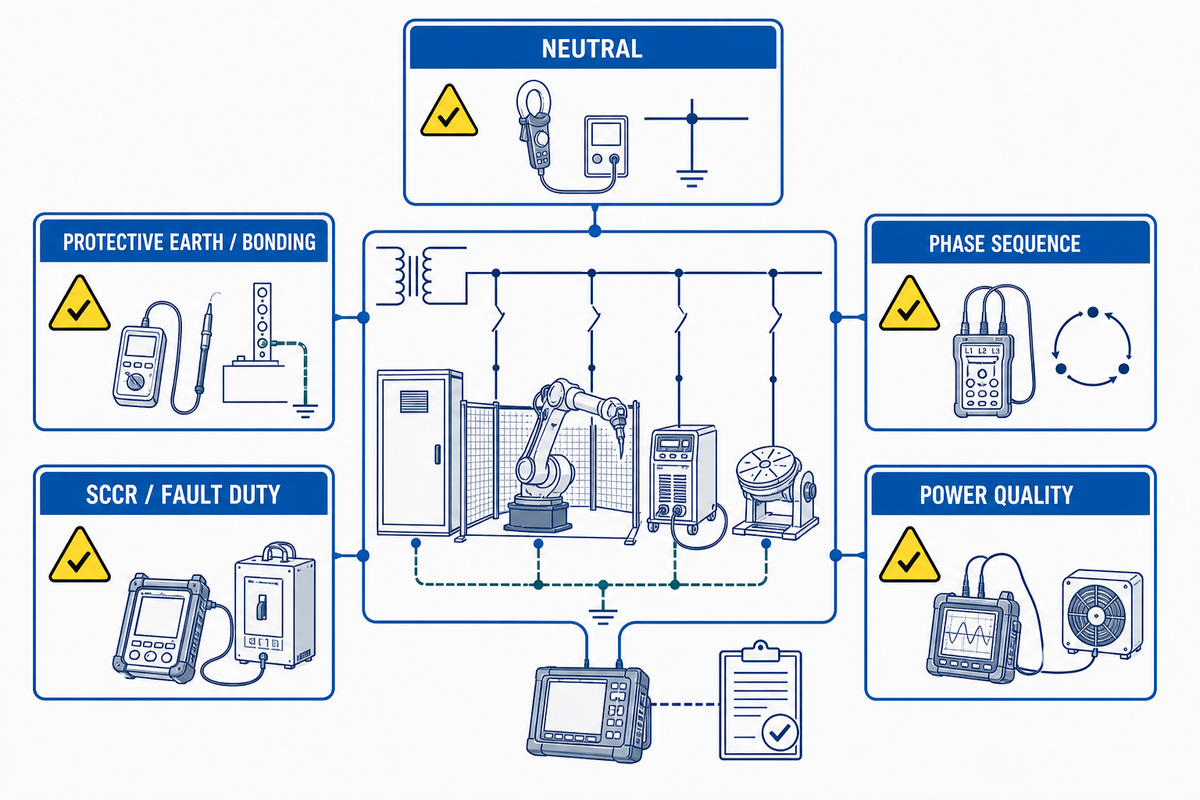
Correct volts and hertz can still leave the cell electrically incompatible. The interface also needs the right conductors, protective bonding, isolation, protection, fault rating, and supply quality.
IEC 60204-1 is a useful framework because it addresses the machine supply connection together with overcurrent protection, protective bonding, short-circuit considerations, EMC, and documentation. Regional code and conformity routes still depend on the installation country.
| Check | Question to close |
|---|---|
| Neutral | Does any control, receptacle, fan, light, or service load require it? |
| Protective earth/bonding | Are all exposed conductive parts and moving sections covered by the approved bonding design? |
| Phase sequence | Which pumps, fans, or other loads require a verified rotation direction? |
| SCCR/fault duty | Is the assembly rating adequate for the available fault current with the specified protection? |
| Power quality | Can the supply remain within the equipment’s approved limits during real plant operation? |
Where the supply is uncertain, measure the parameters that matter instead of relying on a single handheld reading. IEC 61000-4-30:2025 supplies repeatable measurement methods for conducted power-quality phenomena; it does not supply universal equipment acceptance limits.
Inside the plant, the boundary changes again. IEC TS 62749:2026 addresses characteristics at the public-network point of supply, while IEC 61000-2-4:2024 addresses compatibility levels at industrial in-plant points of coupling.
Incoming power is only half the EMC question because the cell also generates disturbances. IEC 60974-10:2020 covers welding power sources and ancillary equipment such as wire feeders and liquid cooling systems; the integrator must coordinate equipment immunity, emissions, the plant environment, and the measurement plan.
Facility-level harmonic review needs its own coupling point and aggregate-load basis. IEEE 519-2022 addresses steady-state distortion at the user point of common coupling; transient overvoltages and other events still require evaluation under the applicable in-plant criteria and measurement plan.
For the demand side, IEC TS 63191:2023 outlines power-quality measurement and assessment within buildings and industrial installations. Measurements at the relevant coupling point may not represent the cell terminals when a long dedicated feeder or a locally generated disturbance changes conditions downstream, so the plan should state where and how long data is collected.
Keep protective bonding separate from the welding work-return circuit. For covered US workplaces, OSHA 1910.254 distinguishes machine-frame grounding, work-return paths, supply conductors, disconnecting means, and overcurrent protection.
“Grounding of the welding machine frame shall be checked.”
Selected equipment, the applicable in-plant class, the site design, and local requirements determine acceptance values. No guide can invent one harmonic, sag, unbalance, or emission limit for every robot cell.
Pre-Shipment RFQ Data to Send the Manufacturer
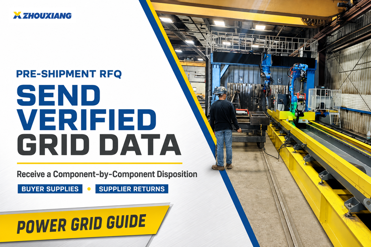
Send verified facility data and require the supplier to return a completed component-by-component disposition. This is cheaper than discovering a frequency-only motor or missing neutral after the cell reaches the factory floor. Those acceptance values now become RFQ inputs rather than generic limits.
Buyer supplies
- Installation country, factory address, point of connection, and target commissioning date
- Measured or utility-confirmed voltage, tolerance, frequency, phase, and conductor arrangement
- Neutral availability, earthing/grounding system, and prospective fault current when available
- Transformer/generator details, voltage-drop concerns, and relevant power-quality history
- Ambient temperature, altitude, dust/moisture conditions, and local electrical/conformity requirements
- Process details that determine the robot, welding package, positioner, extraction, and auxiliaries
Supplier returns
- Completed Grid-to-Arc Power Passport for the exact bill of materials
- Single-line diagram, load list, terminal plan, and approved taps or settings
- Transformer or converter scope, losses, cooling, enclosure, and protection requirements
- Exceptions, local items, required replacement parts, and responsibility boundaries
- Applicable manuals, declarations, test evidence, and commissioning acceptance checks
If your project is still defining the welding application, review the cell architecture before freezing the electrical schedule. Zhouxiang’s manufacturer background provides context for the engineering documentation discussion, but the approved project drawings and exact component manuals must control the connection decision.
Commissioning Checklist Before the First Arc
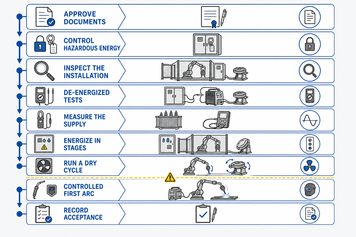
Commission in controlled stages and record the baseline before welding production begins. Do not energize first and use alarms, heat, or motor noise as a compatibility test. Approved RFQ drawings and manufacturer instructions become the commissioning baseline.
- Approve documents: close every passport row, drawing revision, calculation, exception, and responsibility.
- Control hazardous energy: follow the site isolation and lockout/tagout procedure before inspection or service.
- Inspect the installation: check terminals, conductor identification, protection, bonding, work-return routing, cooling clearances, and transformer/converter configuration.
- Complete required de-energized tests: use the applicable design, manufacturer instructions, and local rules.
- Measure the supply: confirm phase-to-phase and relevant phase-to-neutral values, frequency, phase sequence where required, and grounding arrangement.
- Energize in stages: verify panel auxiliaries, controller, drives, extraction, cooling, positioner, and welding power source before a live arc.
- Run a dry cycle: test robot motion, interlocks, communication, torch service, and emergency functions without welding.
- Make a controlled first arc: verify arc start, wire feed, shielding gas, waveform or program selection, and stable operation under the approved WPS.
- Record acceptance: capture supply readings, alarms, thermal observations, configuration backups, and sign-off.
There is no universal commissioning duration because cell complexity, site readiness, code requirements, and unresolved exceptions vary. ISO 10218-2:2025 provides current robot-cell integration context, and covered US servicing work must also observe OSHA 1910.147 hazardous-energy controls.
Robot integration safety is not the entire welding safety case. ISO 10218-2:2025 excludes hazards arising from processing materials such as metal, so the project must separately assess welding fumes, heat, sparks, radiation and other process hazards using the applicable welding and workplace requirements.
Welding packages also have their own equipment standards. IEC 60974-1:2021 covers safety and performance requirements for industrial welding power sources, while IEC 60974-9:2018 covers their installation and use; verify the exact product’s declarations and instructions rather than treating these references as proof of compliance.
Once the electrical baseline is stable, verify that the released welding process programme and communications have survived the change, including Ethernet settings where the exact cell uses them. Run the approved MIG or TIG procedure only as applicable, then compare bead appearance, penetration, heat input and spatter with the qualified procedure instead of tuning around an unresolved supply problem.
Confirm environmental ratings before the load test. OSHA 1910.254 uses 40°C cooling air and 1,005.8m altitude as standard-service examples for arc-welding machines in covered US workplaces; unusual conditions require equipment suited to that service rather than an assumed derating.
Stop condition
Cease commissioning if the measured supply, conductor arrangement, protection, grounding, component rating, or approved paperwork differs from the released design. Correct the discrepancy with the responsible manufacturer, integrator, and electrical professional before proceeding.
Часто задаваемые вопросы
Может ли сварочный робот 380В/50Гц работать на частоте 480В/60Гц?
Not from those two labels alone. Check every powered component for its approved voltage, frequency, and phase range. Voltage transformation may resolve a mismatch only when the affected loads accept the available frequency. If any controller, motor, fan, chiller, or positioner is 50Hz-only, obtain manufacturer approval for active conversion, replacement, or redesign before ordering or energizing the cell.
Изменяется ли трансформатор на 50 Гц до 60 Гц?
No; a passive transformer changes voltage, while its output frequency follows its input frequency. Use it only when each downstream load is approved for the available frequency. True 50-to-60Hz or 60-to-50Hz mismatches need approved active frequency conversion, a different component, or a redesigned supply agreed by the manufacturer and integrator. Schneider Electric explains this distinction in its transformer frequency guidance.
What electrical data should I send before ordering a welding robot?
Send the measured or utility-confirmed line voltage, frequency, phase, conductor arrangement, neutral availability, grounding system, prospective fault level, and relevant power-quality history. Add one row for every cell load with model, input rating, current or kVA, inrush, and duty. Ask the supplier to return an approved connection method, protective requirements, drawings, and commissioning tests for every row. Include the process and workpiece data needed to freeze the final cell bill of materials.
Can a multi-voltage welding power source solve the whole cell?
No; it solves only its own documented input requirement. The robot controller, positioner, extraction fan, chiller, torch service station, safety devices, and panel auxiliaries keep their own ratings.
Use the exact bill of materials to confirm each load. Broad input range on one device is helpful, but it is not a cell-level approval.
Is 220V single-phase enough for a welding robot cell?
Only if every component and the integrated design are explicitly approved for that service and the available capacity is adequate. Many industrial cells use three-phase primary power or multiple derived supplies, so voltage alone cannot answer the question by itself.
Match the Grid Before You Choose the Cell
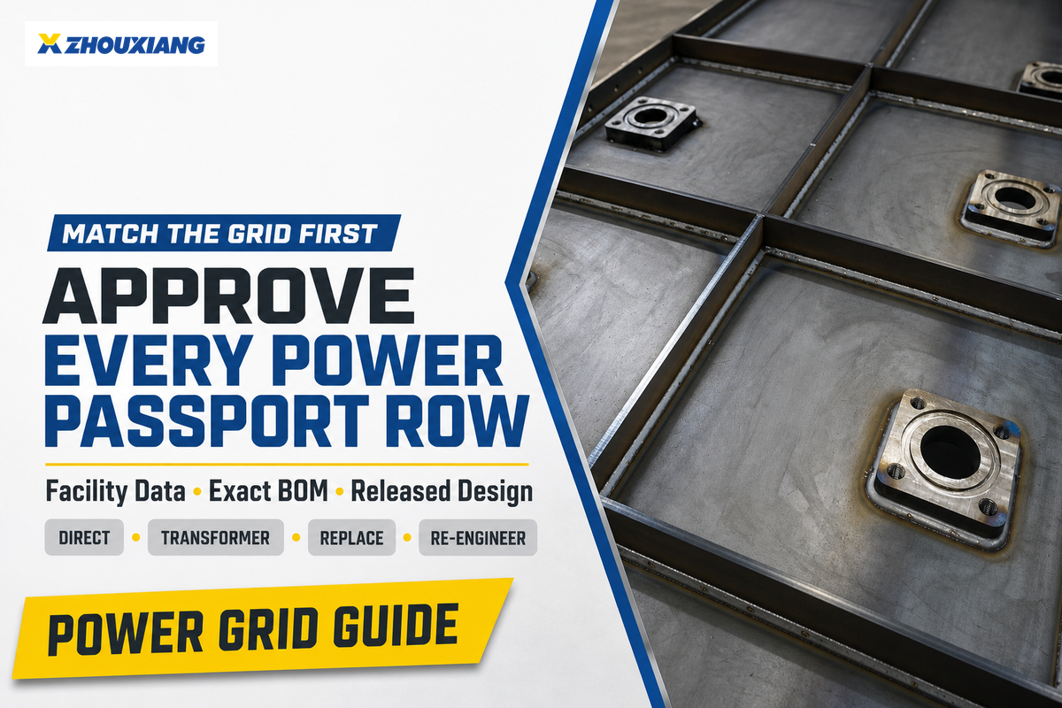
Start with facility data, follow with the exact cell bill of materials, and approve one Power Passport row for every load. That sequence tells you whether the project belongs in the direct, transformer, replace, or re-engineer lane before equipment ships.
Once the electrical boundary is defined, move to application and configuration selection with the structural-steel solution team. Keep the released single-line diagram, settings, test records, and manufacturer approvals with the cell so future service or relocation does not reopen the same compatibility risk.
References and Sources
- ISO 10218-2:2025 – industrial robot applications and robot cells
- IEC 60204-1, electrical equipment of machines
- IEC 61000-4-30:2025, power-quality measurement methods
- IEC 61000-2-4:2024, industrial in-plant compatibility levels
- IEC TS 63191:2023 – demand-side power-quality measurement planning
- IEC 60974-10:2020, welding-equipment EMC requirements
- IEC 60974-1:2021, welding-power-source safety and performance
- IEC 60974-9:2018 – installation and use of arc-welding equipment
- IEC TS 62749:2026, public-network supply characteristics
- IEEE 519-2022 – steady-state distortion at the point of common coupling
- OSHA 1910.254, arc welding and cutting
- Schneider Electric, transformer frequency guidance
Сейчас популярно