Entre em Contato com Zhouxiang

Especificações rápidas
| Largura de soldagem de pórtico | até 5.000 mm |
| Tolerância de ajuste | ~1,5 mm em um caminho programado; +/-3 mm com rastreamento adaptativo de costura a laser |
| Linha de base manual (costuras retas do tanque) | 57 horas/unidade; o ciclo robótico reduz isso para cerca de metade |
| Janela típica de retorno | 10-20 meses para células comparáveis de fabricação de equipamentos de energia |
| Código de solda governante | AWS D1.1/D1.1M:2025, além de um padrão de estanqueidade ao tanque específico da classe (veja abaixo) |
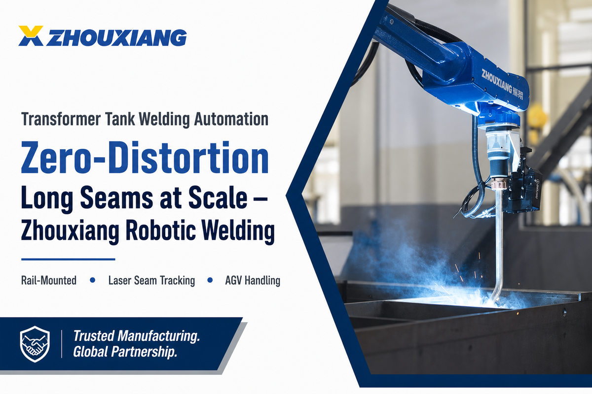
A automação de soldagem de tanque transformador é o uso de células de soldagem robóticas montadas em trilho, pórtico ou cantilever, emparelhadas com rastreamento de costura a laser e AGVs, para realizar soldagem totalmente automática no corpo do tanque principal, aletas de resfriamento corrugadas e costuras de cobertura de um tanque de óleo para um transformador de potência ou distribuição Não é difícil executar um robô perfeitamente por uma costura reta; o verdadeiro desafio é manter a precisão dimensional em uma estrutura de aço grande e um pouco flexível enquanto solda vários metros de costura sem deformação suficiente para comprometer a vedação estanque a óleo ou o ajuste do núcleo e enrolamento no interior.
Uma célula de soldagem de tanque de transformador de nível de produção pode empregar um pórtico ou robô montado em trilho junto com rastreamento de costura a laser, uma sequência de solda controlada por distorção e manuseio estação a estação baseado em AGV Em vez das cerca de 57 horas que pode levar para soldar uma costura reta em um tanque manualmente, um sistema acionado por robô pode levar apenas metade desse tempo E em vez de uma taxa de rejeição de 5 a 101TP3 T em um tanque produzido manualmente, a taxa de rejeição pode cair abaixo de 2%.
Mas três outros parâmetros realmente determinam se aquele “half” ou “sub-2%” se torna realidade, e explicarei cada um por sua vez, abaixo.
O que a automação da soldagem de tanques de transformadores realmente envolve e por que é um problema diferente do aço estrutural
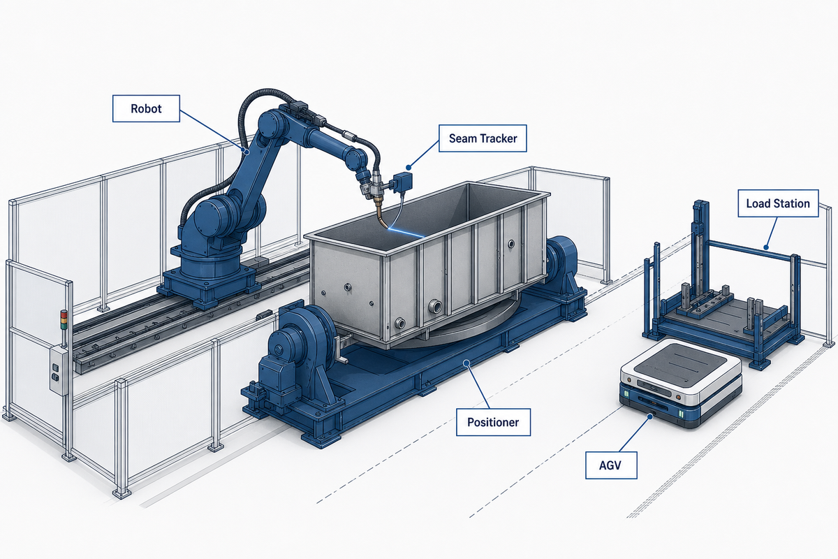
Uma linha de soldagem de tanque de transformador completo é um maquinário complexo com cinco partes móveis: um braço robótico servo-acionado montado em trilho, pórtico ou cantilever; um cabide ou posicionador invertido giratório para soldas planas e horizontais; um sensor de rastreamento de costura a laser ou de visão 3D para correção de tocha em tempo real; um AGV ou guindaste movendo o tanque entre as estações; e um controlador executando um módulo de importação CAD sem ensino ou programas de caminho off-line reproduzidos.
Essa descrição corresponde à visão geral da IA do próprio Google para este tópico, mas não explica por que um tanque transformador é um problema de soldagem mais difícil do que uma estrutura de aço padrão. Cada um desses cinco elementos, desde o robô até o controlador, ainda precisa ser integrado aos requisitos de avaliação de segurança de ISO 10218-2:2025 antes de soldar uma única costura A tecnologia de rastreamento de costura, em particular, deve manter a precisão de alta precisão em toda a área de soldagem, não apenas no momento da instalação, ou os ganhos de automação descritos abaixo evaporam.
A página de equipamentos de energia Zhouxiang sobre soluções explicita o requisito simplesmente: Tanques, caixas de quadros e estruturas de geradores devem manter tolerâncias dimensionais “tight” com soldas “uniformes e baixa distorção.” Esse é um padrão uma ordem de magnitude maior do que a repetibilidade da solda de filé que normalmente forma o ROI para aço estrutural automatizado A distorção em forma de tanque tem três desafios adicionais: as soldas devem efetivamente ser estanques a óleo (a varredura em um transformador cheio de óleo é uma reivindicação de garantia, não um defeito cosmético); os corpos dos tanques são geralmente grandes e relativamente finos em comparação com seu comprimento e tendem a deformar; e há uma folga pré-determinada para o núcleo e as bobinas dentro das quais as paredes distorcidas podem reduzir.
A sequência de solda que controla a distorção em costuras retas longas
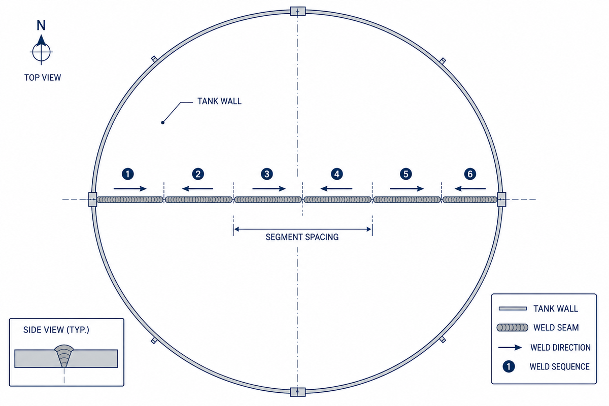
Nenhuma pesquisa acadêmica publicada examina as costuras do tanque especificamente o controle da distorção no seguimento da discussão é tirada do trabalho geral da distorção da fabricação do aço (painéis do navio, vasos de pressão, estruturas de mineração) Nenhum estudo dedicado do transformador-tanque existe porque o problema subjacente é o mesmo: soldar costuras longas no aço grosso sob a restrição Esta discussão é apresentada diretamente, sem vestir-se acima como a pesquisa tanque-específica.
A soldagem back-step e skip são as duas técnicas de sequenciamento padrão para uma costura longa e significam algo específico: a soldagem back-step deposita segmentos curtos na direção oposta à progressão geral da solda, enquanto a soldagem skip apresenta execuções curtas e espaçadas uniformemente aproximadamente o comprimento do escoamento natural de um eletrodo, de acordo com Orientação de controle de distorção de fabricação do TWI. Um exemplo trabalhado concreto dos engenheiros de soldagem da Lincoln Electric: em uma junta soldada com back-step, os segmentos correm cerca de 1 polegada (2,5 cm) de comprimento; prenda as extremidades primeiro, depois volte de uma extremidade em direção à aderência Esta técnica cancela especificamente a distorção rotacional (a abertura ou fechamento da junta) e não corrige outros modos de distorção, portanto, escolhê-la para o modo de falha errado desperdiça o esforço.
2,5 cmcomprimento padrão do segmento de back-step
60.71%distorção cortada apenas por fixação em um teste revisado por pares de 2026
150-350mmcomprimento do segmento de solda de salto em uma patente robótica de soldagem de tanque de 2025
Uma descoberta contra-intuitiva a ter em mente antes de programar uma célula automatizada com uma sequência de soldagem específica é que sua escolha de padrão é muito menos importante no chão de fábrica do que geralmente se acredita. Cinco sequências de solda diferentes aplicadas a uma estrutura de parede lateral reforçada com 6 m foram testadas em um artigo da ASME Pressure Vessels & Piping Conference de 2009 e resultaram em apenas uma variação de 7,65-10,2 mm na distorção espalhada entre elas (uma faixa modesta e orientada pela geometria, em vez de uma diferença de ordem de magnitude. Talvez mais reveladora, uma revisão por pares de 2026. Papel Estruturas Marinhas que usou um experimento de soldagem mecanizada real para validar um modelo termo-elasto-plástico de elementos finitos relatou que uma sequência de soldagem simples sem backstep com um acessório de restrição de modelo melhorou o deslocamento do ponto máximo em 60,711TP3 T (de 42 mm para 16,5 mm) enquanto superava os padrões de centro para fora e backstep em termos de tempo de ciclo e distorção Implicação prática para uma linha de tanque automatizada: controlar a disciplina de fixação é tão importante, se não mais importante, do que qualquer sequência específica que você programa em seu robô, como mostrado em um chinês de 2025 robô soldagem pedido de patente (CN121733075A) que apresenta um caminho de soldagem intermitente unidirecional com segmentos de 150-350 mm e espaços entre segmentos adjacentes de mínimo de 500 mm para distribuir a entrada de calor, combinado com uma pré-cambagem mais estrutura de retenção rígida externa para manter a planicidade da parede dentro de 3/1000 e verticalidade pós-montagem dentro de 3 mm.
Vantagens de uma abordagem de sequência mais fixação
- A ordem de solda repetível remove a variação operador a operador
- Combinada com restrições rígidas, a distorção cai muito mais do que apenas a escolha da sequência
- O espaçamento entre entradas de calor (500 mm+ entre segmentos) é programável e executável, ao contrário do espaçamento manual
– Limitações
- O back-step apenas corrige a distorção rotacional; não fixará o arqueamento ou a distorção angular de outras causas
- O benefício da sequência depende da geometria; a mesma sequência pode ter desempenho inferior em um layout de tanque diferente
- A fixação que não é rígida o suficiente nega a maior parte do benefício da sequência
As oficinas que ajustam a sequência de solda à geometria específica do tanque, em vez de copiar uma receita genérica de um fabricante diferente, adaptam-se mais rapidamente quando um novo modelo de tanque entra em ação.
“Nossos conjuntos fixos, devido aos empilhamentos de tolerância e à distorção transmitida pelo pré-aquecimento e pela deposição das soldas multipasse, podem fazer com que a localização da junta de solda varie até 0,5 pol. ... desenvolver o procedimento para localizar com precisão as juntas de solda no espaço é a única maneira de fazer o processo funcionar.”
Escolhendo Programação sem ensino, offline ou manual para variedade de tanques
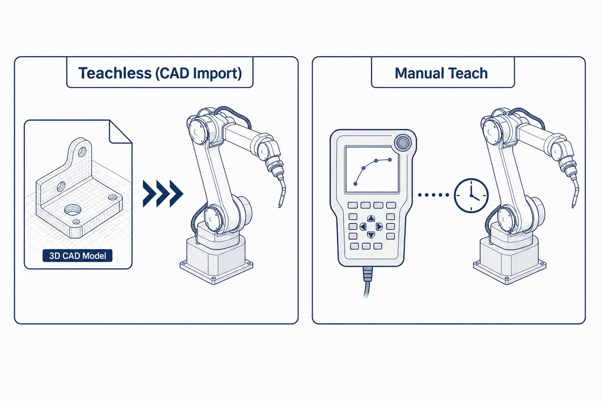
A escolha de programação sem ensino, off-line ou manual para uma linha de produção de tanques de transformadores se resume a quantos modelos de tanques distintos a linha processa: a produção de alta mistura favorece a programação de importação de CAD sem ensino, um modelo de repetição fixa favorece caminhos programados off-line reutilizáveis e um verdadeiro one-off pode precisar de ensino manual com assistência a laser como alternativa.
Em um artigo revisado por pares de 2011 do laboratório de soldagem robótica da Universidade de Wollongong, a Programação Offline Automatizada reduziu o tempo de programação de um sistema de 6 robôs e 13 graus de liberdade (eixos) para menos de cinco minutos por costura de solda, de mais de seis meses antes, após um investimento inicial de quatro semanas para estabelecer um modelo de processo, um custo que só faz sentido economicamente se houver variedade de modelo suficiente para justificá-lo.
Este ponto de dor é concreto, não teórico; no fórum integrador da Universal Robots, um engenheiro trabalhando em uma tarefa de solda de 210 pontos recorreu à medição e entrada de cada posição de solda a partir de CAD à mão, uma vez que nenhuma transferência direta de caminho CAD para robô estava disponível, que é exatamente o cenário que a programação sem ensino visa eliminar. Entrevistas com fornecedores sugerem uma economia de tempo potencial na ordem de aproximadamente 70% para instância, um fabricante de alto mix quantificou uma diferença entre a programação do chão de fábrica, a programação do scratch e a programação offline em 4 dias versus 2 semanas para um grande programa de vários milhares de linhas. Use esses números específicos do fornecedor direcionalmente.
📐 Nota Engenharia
Qualquer instalação de robô de soldagem requer uma avaliação de segurança de acordo com ISO 10218-2:2025 (a versão atual do padrão de segurança de aplicativos robóticos, que substitui a versão retirada de 2011).A programação sem ensino altera a velocidade de reprogramação da célula; não a isenta de ter sua zona de segurança reverificada toda vez que o caminho de soldagem ou os acessórios são alterados.
Escolher um sensor de rastreamento de costura para a mesma linha é importante por um motivo relacionado, mas diferente; não se trata de detectar a costura uma vez; trata-se de manter essa precisão durante meses de produção. Os rastreadores a laser e de visão 3D corrigem o caminho da tocha em tempo real tanto para as longas costuras retas do corpo do tanque quanto para as juntas mais curtas da aleta ondulada, mas o sensor é tão bom quanto seu estado de calibração; interferência na superfície reflexiva, respingos de solda na lente e desvio entre os ciclos de recalibração corroem a precisão da soldagem que uma folha de especificações promete no primeiro dia, razão pela qual um cronograma de manutenção para a janela do sensor pertence à mesma conversa que a decisão do método de programação, e não a separada.
Soldagem de aletas e radiadores corrugados versus costuras principais do corpo do tanque
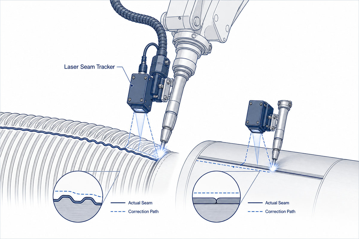
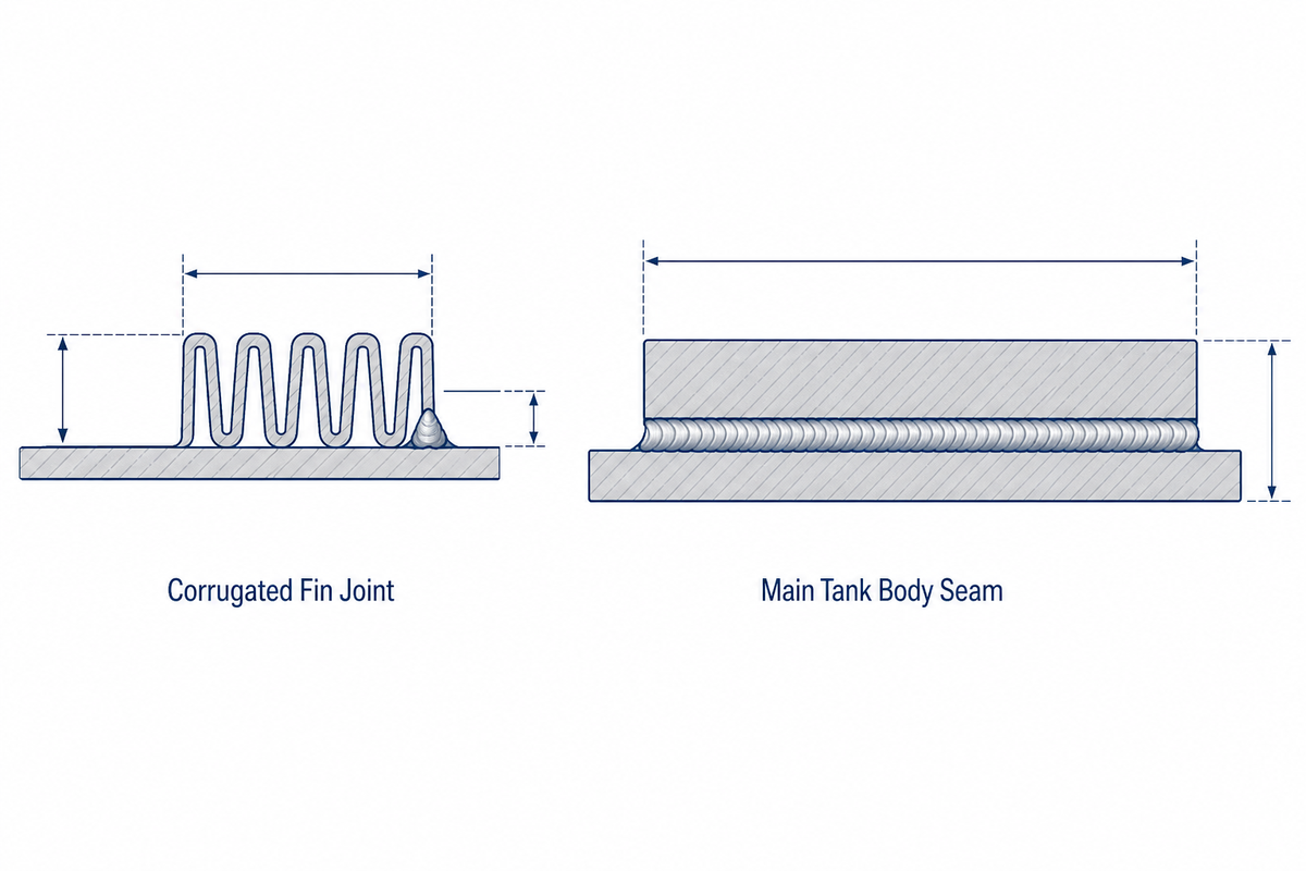
A soldagem de aletas onduladas geralmente é executada como seu próprio processo dedicado, não uma reflexão tardia na célula robótica principal do corpo do tanque O equipamento especializado para ela (Soldadores de costura de aletas CMT ou TIG) é vendido como uma classe de máquina distinta porque o processo de soldagem e a geometria da junta são genuinamente diferentes: costuras curtas, frequentes e de bitola fina, em vez de algumas corridas longas e grossas.
As especificações do equipamento da indústria geralmente citam velocidades de soldagem de aletas na faixa de 3-4 aletas/minuto em aço carbono de 1-1,5 mm com uma folga de aleta de 6-8 mm antes da soldagem, um problema de cadência diferente de uma única costura de corpo de tanque de vários metros inteiramente.
Vale a pena levar uma lição de qualidade para a documentação do equipamento da linha de transporte para qualquer célula automatizada; conectar os elementos da aleta ao tubo de coleta de óleo historicamente usou uma solda interna, que prendeu resíduos de solda e sucata de ferro dentro do canal. Uma junta documentada. Mudar essa solda externa com proteção de CO2 eliminou totalmente o problema de resíduos e proporcionou qualidade estável em toda a passagem da aleta, verificada em relação a um padrão de teste da indústria de transformadores por meio de vedação de terceiros e verificações de lavagem com óleo quente.
É um pequeno detalhe do processo, mas é exatamente o tipo de correção específica que separa uma linha de aletas genuinamente projetada de uma célula de soldagem genérica reaproveitada para o trabalho de aletas As soldas de aletas também são soldas estruturais e se enquadram nas mesmas AWS D1.1/D1.1M:2025 guarda-chuva de critérios de aceitação como as principais costuras do corpo do tanque, embora a geometria da junta e o tempo de ciclo sejam totalmente diferentes.
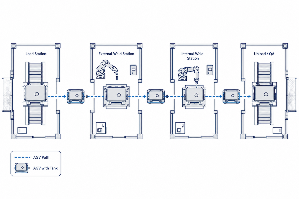
Manuseio de materiais entre estações de carga, solda externa e solda interna
- Estação carga; o invólucro e a tampa do tanque fabricados são montados e fixados antes do início de qualquer passagem de solda.
- Estação de solda externa; o robô completa as costuras externas (corpo, flange de cobertura, pontos de fixação da aleta ondulada) enquanto o tanque é mantido em um posicionador ou cabide giratório.
- Estação de solda interna; uma passagem separada atinge reforços internos e defletores que ficam inacessíveis quando a tampa é fechada.
- Descarregar/descarga de controle de qualidade; o tanque concluído passa para a verificação da estanqueidade (veja abaixo) antes da montagem final.
O manuseio de materiais tem que acompanhar o ritmo das células do robô, ou essas quatro estações não funcionam como produção automatizada Obter um casco de tanque de várias toneladas entre elas sem um guindaste em cada ciclo é o que os AGVs servem O NIST, citando dados da OSHA, relata uma fatalidade relacionada à empilhadeira aproximadamente a cada três dias nos EUA, com cerca de 80% dos cerca de 11.000 acidentes anuais com empilhadeiras envolvendo um pedestre. O caso de segurança para manuseio automatizado não é hipotético.
Padrão Internacional Atual ISO 3691-4:2023 afirma que os sistemas de detecção de obstáculos e pára-choques de caminhões sem motorista devem garantir que não mais do que 135 N de força sejam exercidos contra uma pessoa ou obstáculo quando parado, o que é muito mais objetivo do que apenas uma parada segura.“ AGVs pesados, transportando cargas muito maiores do que um tanque transformador, estão comercialmente disponíveis até aproximadamente 800 toneladas de capacidade, portanto a carga geralmente não é o limite; integrar o AGV com a zona com classificação de segurança da própria célula de soldagem sob a ISO 10218-2:2025 geralmente é.
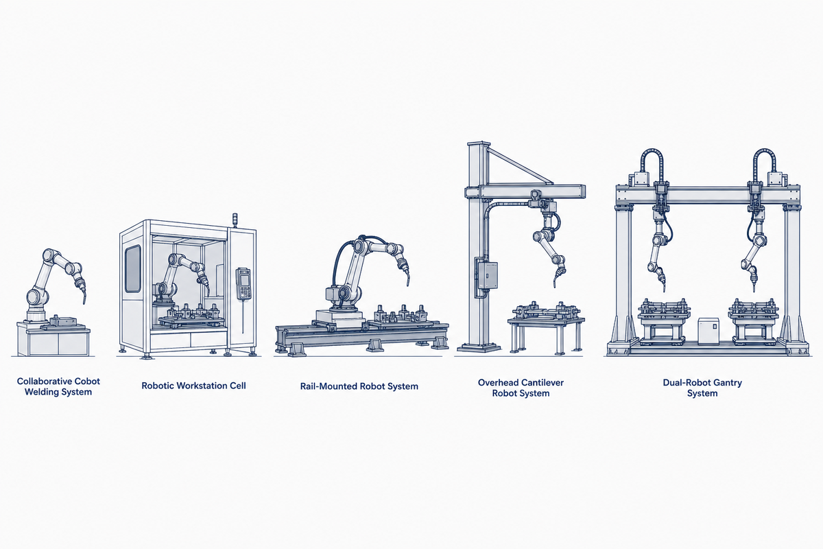
Correspondendo a arquitetura do sistema ao tamanho e volume do tanque
O Limiar de ajuste da linha do tanque de 5 arquiteturas abaixo alinha o nível de produção e o tamanho do tanque com uma das cinco arquiteturas de sistema, usando os suportes de custo e limites de desempenho que a Zhouxiang publica para suas linhas de células montadas em trilhos, pórticos, cantilever, cobot e estações de trabalho.
Essa é uma decisão de produção fácil de errar em qualquer extremidade, porque subespecificar e especificar demais o sistema desperdiça tanto o capital como uma célula montada em trilho percorre o robô ao longo de um trilho-guia fixo, trocando flexibilidade pela velocidade de costura reta, enquanto um pórtico ou célula cantilever troca alguma dessa velocidade por uma cobertura mais ampla e qualquer arquitetura em que você ainda precise atender à mesma ISO 10218-2:2025 requisitos de segurança de integração celular abordados acima.
| Nível/perfil de produção | Arquitetura recomendada | Faixa de preços indicativa (USD) | Limitações /Não adequado para |
|---|---|---|---|
| Baixo volume, variedade de tamanho de tanque alto, mistura de oficina | Robô de soldagem colaborativo (cobot) | $10,000-20,000 | Não classificado para produção contínua em 3 turnos; ciclo mais lento que sistemas ferroviários fixos |
| Volume médio, lotes padrão da aleta/painel | Estação de trabalho inteligente da soldadura | $22,500-30,000 | Pegada fixa da pilha; não adequado para tanques que excedam a capacidade do posicionador da estação |
| Costuras retas longas, robô único, volume moderado | Robô de soldagem montado em trilho | $38,500-65,000 | O comprimento do trilho é fixado na instalação; não é adequado para comprimentos de tanque muito variados sem reconfiguração |
| É necessário lote de alto volume e carregamento de ponte rolante | Robô solda cantilever | $46,000-50,000 | A configuração da viga aérea precisa de altura de teto adequada; menos eficiente em termos de espaço do que os sistemas ferroviários para lojas estreitas |
| Tanques de placa larga, dual-robô, maior volume | Robô de soldagem de pórtico (duplo robô capaz) | $77,000-80,000 | Maior custo de capital; subutilizado em operações de tanques pequenos ou pouco frequentes |
| Tolerância de ajuste em todos os níveis | ~1,5 mm em um caminho programado; +/-3 mm com rastreamento de costura a laser adaptativo | ||
| O preço base inclui | Braço do robô, controlador, fonte de energia de soldagem, acessórios padrão, cabeamento, supervisão de instalação, treinamento do operador | ||
| Preço como opções | Rastreamento de costura, visão 3 D, software de programação offline, acessórios personalizados | ||
Verificação de qualidade e estanqueidade de solda
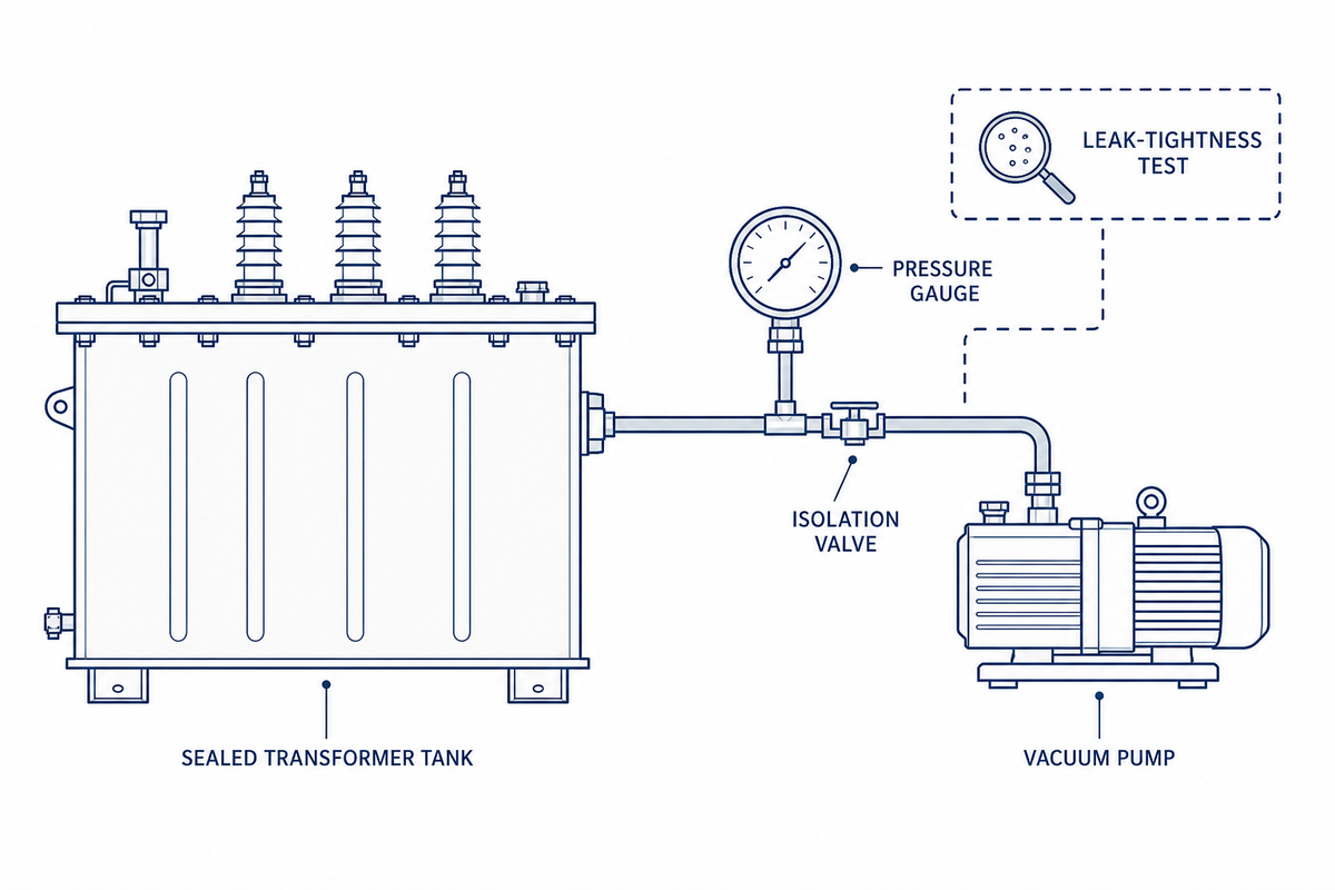
A qualidade da solda na própria junta é regida pelo AWS D1.1/D1.1M:2025, o Código de Soldagem Estrutural (Structural Welding Code) (Structural Welding Code (Structural Welding Code) (That code sozinho não demonstra o óleo do transformador de vazamento do tanque acabado que ganhou um teste separado e específico do tanque.
A atualização de 2025 para AWS D1.1 adicionou tabelas de procedimentos de soldagem pré-qualificados cobrindo processos de não curto-circuito e arco pulsado, que compõem a maioria das solda robótica de costura de transformador-tanque, além de especificações revisadas de tratamento térmico e critérios numéricos de aceitação de porosidade.
Aqui está uma nuance que vale a pena acertar em vez de papering over: IEEE C57.12.00 contém apenas um limite superior geral de 2 atm absoluto para a pressão de um tanque selado & number e sua própria redação adia os valores específicos de teste de estanqueidade e teste de vácuo para o padrão companheiro específico do tipo aplicável Esse padrão companheiro específico do tipo realmente define os requisitos estruturais e de alívio de pressão do tanque, IEEE C57.12.39, é escopo estritamente para transformadores de distribuição que são imersos em óleo, e assim não, por sua própria declaração, se estendem a classes de tanques de potência e grandes transformadores Para um tanque de classe de distribuição, o teste de estanqueidade do fabricante normalmente implica um vácuo-hold ou um teste de pressão-hold, como, na prática de aquisição de petróleo e gás, “deve manter vácuo total a pressão externa igual a 1 atm manômetro Os critérios de desempenho para tanques grandes geralmente serão estabelecidos de acordo com os requisitos gerais do IEEE C57.12.00 mais ASME Código de Caldeiras e Vasos de Pressão” Não há um padrão complementar específico comparável Vale cinco minutos extras para verificar se os requisitos gerais do C57.12.00 mais o Código ASME BV & PV são a rota apropriada para definir o teste do tanque a partir desse limite geral para fora para sua classe específica, pois assumir C57.12.39 se aplica a todas as classes é o tipo de slip-up que vem para auditoria leve.
Custo e retorno para uma linha de soldagem de tanque transformador
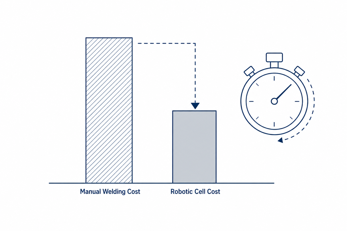
Quer o chão de fábrica o chame de robô de soldagem, máquina de soldagem robótica ou simplesmente soldagem para produção de tanques de transformadores, os robôs industriais oferecem a mesma matemática de retorno de alta eficiência: uma solução de soldagem automatizada aumenta a produtividade por turno com um processo mais inteligente e repetível do que soldagem manual, independentemente da etiqueta da célula.
Em geral, a soldagem a arco industrial, uma célula robótica produz cerca de 6.000 a 12.000 kg de metal de solda por robô anualmente, contra 1.500 a 2.000 kg para um soldador manual, de acordo com o gerente de automação da Kemppi escrevendo na ASSEMBLY Magazine uma lacuna de 3 a 6 x antes de contar o tempo de inatividade ou retrabalhar diferenças.
Esse hiato de produção é o principal impulsionador da eficiência por trás da automação e agrava um fator de custo subabordado: a American Welding Society projeta um déficit de 330.000 soldadores até 2028, e um aumento anual de custos de mão de obra qualificada de 7-15% corrói o retorno de atrasar a automação, não apenas o seu preço de compra.
No lado do retrabalho, uma soldagem robótica em tanque com arquivo de 2025 patente path-planning afirma que sua abordagem de controle de distorção e correção de chama de mão de obra (trabalho de correção de chama) tradicionalmente chega a 700 T de mão de obra total em um tanque soldado manualmente (corta no mínimo, uma linha de custo oculto, um cálculo simples de horas economizadas perde.
Custo de propriedade de 5 anos: célula montada no total versus soldagem manual contínua (lustrativo volume de um tanque/dia)
| Artigo de custo | Célula robótica montada em trilho | Soldagem manual (2 soldadores) |
|---|---|---|
| Preço de compra | $38,500-65,000 | $0 (mão de obra existente) |
| Instalação e comissionamento | Incluído no preço base | n/a |
| Mão de obra (5 anos) | 1 operador gerenciando a célula | 2 soldadores, inflação salarial de 7-15%/ano |
| Fio e gás (5 anos) | 10-251TP3 T menor consumo por unidade soldada | Linha de base |
| Risco de retrabalho/tempo de inatividade (5 anos) | Sob a taxa de rejeição 2% | Taxa de rejeição 5-10% |
Exemplo de retorno: a uma taxa de mão de obra totalmente carregada de $30/hora e dois soldadores substituídos por um operador mais uma célula montada em trilho $50.000, somente a economia anual de mão de obra é executada na faixa $80.000-150.000 citada em todo o setor para uma troca de automação unicelular; contra um custo instalado de $50.000-65.000, só isso cai dentro da janela de retorno de 10 a 20 meses comumente relatada antes que as economias de fio, gás e retrabalho sejam adicionadas no topo. Execute seus próprios números com o calculadora ROI robô soldagem antes de se comprometer com uma arquitetura específica.
A crise na oferta de transformadores está remodelando as prioridades de investimento em automação
Em julho de 2026, a história de fornecimento do transformador não era uma crise unificada. Ela se divide de forma limpa por classe de transformador, uma divisão com implicações reais para a qual os segmentos estão realmente vendo benefícios de capacidade impulsionados pela automação no momento.
Os transformadores de energia e de aumento de gerador (GSU) permanecem em uma restrição severa de fornecimento de vários anos: a demanda dos EUA por transformadores de energia aumentou 1161TP3 T desde 2019 e a demanda por transformadores de distribuição aumentou 411TP3 T, com déficits de fornecimento de 2025 estimados em 30% para energia e 10% para distribuição figuras do próprio comunicado de imprensa de agosto de 2025 da Wood Mackenzie, verificadas diretamente em vez de tomadas em segunda mão.
Outra cobertura da imprensa especializada da mesma pesquisa cita o crescimento da demanda da GSU tão alto quanto 2741TP3 T, um número não presente no próprio lançamento de Wood Mackenzie e que vale a pena tratar com algum ceticismo A Relatório do Conselho Consultivo Nacional de Infraestrutura de junho de 2024 o Presidente descobriu separadamente que os tempos de espera aumentaram de meses em 2020 para dois a quatro anos em 2024, com grandes tempos de energia e de entrega da GSU com uma média de 120-144 semanas.
Os fabricantes estão gastando perto de $22 em energia doméstica nova ou expandida 1 Hitachi Energy, Siemens Energy, Eaton, Prolec GE, Virginia Transformer e cerca de seis outras empresas (uma corrida de capacidade entre fabricantes de transformadores de potência e fornecedores de transformadores que fizeram a soldagem rendimento uma variável competitiva, não apenas uma linha de custo.
Potência /GSU /transformadores de subestação
- Demanda +116% desde 2019 (Wood Mackenzie); a imprensa especializada cita até +274% para GSU especificamente
- Prazos de entrega 120-144 semanas
- Déficit de oferta de 2025 modelado em 30%
- Crunch ainda ativo a partir de dados de 2025
Transformadores distribuição
- Demanda +41% desde 2019 (Wood Mackenzie); Déficit de 2025 modelado em 10%
- Prazos de entrega “normalized” por DOE, março de 2026
- Os gargalos no nível do componente persistem (supressores de raios, disjuntores secundários)
- Melhorando, não totalmente resolvido
Essa diferenciação vem de a Março de 2026 Webinar sobre transformadores de distribuição do Departamento de Energia, onde Prolec GE disse ao painel que “lead times on distribution transformers...retornaram a níveis mais normais nos últimos vários meses,” embora tenha admitido que alguns componentes especiais ainda estão atrasados Na verdade, nem todos no mercado estão de acordo sobre a gravidade da escassez: um corretor de transformadores que foi entrevistado para o artigo Wood Mackenzie afirma que a história da escassez é uma manobra exagerada dos vendedores para inflar os preços, argumentando que um transformador de potência de subestação convencional ainda pode ser encomendado dentro de 12 a 14 meses após a aprovação dos documentos de projeto e que é a utilidade/EPC processos de compra (não restrições de fábrica) que constituem o impedimento realQualquer explicação prova mais próxima da marca, para uma loja de fabricação que cai em ambos os lados do mercado de transformadores, o efeito é o mesmo: A capacidade de soldagem tornou-se um fator competitivo em lead times, ao lado do custo, entre os OEMs de transformadores, e se você pode aumentar a produção de fundição de tanques em curto prazo, você está perdendo mais rapidamente o segmento de energia GSU e expandindo rapidamente o mercado.
Levantamento chave
Os prazos de entrega do transformador de energia ainda estão funcionando há mais de 120 semanas, contra um aumento de 116% desde 2019 (Wood Mackenzie), enquanto os prazos de entrega do transformador de distribuição foram especificamente normalizados de acordo com a atualização de março de 2026 do DOE, o que significa que a capacidade de soldagem de tanques agora é mais importante para OEMs que competem no segmento de energia e GSU.
Perguntas frequentes
Q: Pode personalizado ou não-padrão transformador tanque projetos ser soldado roboticamente?
Sim, a programação sem solda importa um modelo CAD 3D diretamente e identifica as costuras de solda automaticamente, sem um caminho pré-ensinado fixo, e para um tanque único sem arquivo CAD, uma varredura de visão 3D pode gerar o mesmo caminho de solda a partir do físico. parte.
A fabricação de tanques personalizada e não padronizada de hoje depende do controle de soldagem sem ensino; em vez disso, o sistema importa um arquivo CAD 3 D (do SolidWorks, Tekla ou UG, por exemplo), identifica os locais da costura e calcula o caminho de solda, sem pré-ensino manual de uma rota Para um tanque verdadeiramente único, onde um modelo CAD não está disponível, os sistemas de visão 3 D podem ser usados para escanear a peça de trabalho física e construir uma nuvem de pontos, gerando diretamente um caminho de solda a partir da varredura.
Q: Que manutenção os robôs de soldagem de tanques de transformadores exigem?
A manutenção de rotina de consumíveis e a óptica do sensor de rastreamento de costura, o próprio braço do robô, os rolos de soldagem, os revestimentos da tocha, os bicos de contato e a unidade em si, são substituídos de acordo com um cronograma, e as janelas do sensor precisam de limpeza periódica para manter as leituras precisas.
Revestimentos de tochas de soldagem, pontas de contato, bicos e rolos de acionamento são peças consumíveis que devem ser trocadas a uma taxa especificada; enquanto as janelas dos sensores de rastreamento de costura devem ser limpas em intervalos regulares para garantir leituras precisas de uma visão ou laser. A maioria dos bons fornecedores de sistemas mantém um inventário adequado desses consumíveis básicos para poder enviar dentro de 48 horas, e as peças mecânicas/elétricas geralmente estão sob garantia de um a dois anos.
Q: Quanto tempo uma linha de solda do tanque do transformador leva para pagar de volta?
O retorno para uma célula dedicada geralmente cai na faixa de 10 a 20 meses para automação comparável de fabricação de equipamentos de energia, impulsionado por um intervalo de saída de 3 a 6 vezes por soldador, além de custos mais baixos de retrabalho e consumíveis quando a linha estiver funcionando.
Com uma pessoa operando uma ou duas células robóticas no chão de fabricação, várias células de solda manual são substituídas, o uso de fio e gás de proteção cai em 10-251TP3 T e o retrabalho cai do 5-101TP3 T encontrado nas peças manuais para menos de 21TP3 T nas peças do robô A saída por robô por ano também é três a seis vezes maior que a de um soldador manual, que se multiplica no cálculo de retorno junto com a economia de mão de obra no retrabalho e consumíveis Os períodos de retorno do mundo real variam descontroladamente dependendo da sua taxa de trabalho por hora, número de turnos, nível de rejeição manual e do número de modelos de tanques para os quais uma única célula de trabalho robótica será usada (sem um programa completo).
Q: Que qualidade de solda ou padrão de estanqueidade se aplica às soldas do tanque do transformador?
AWS D1.1/D1.1M:2025 governa a própria solda; IEEE C572.39 rege a estanqueidade do tanque para transformadores da classe de distribuição especificamente energia e tanques de grande transformação percorrem o IEEE C57.12.00, além do código ASME de caldeiras e vasos de pressão.
A própria qualidade da solda é geralmente verificada em relação ao perfil de solda AWS D1.1/D1.1 M:2025 e defeitos de solda O IEEE C57.12.39, um companheiro do IEEE C57.12.00, define os requisitos de estanqueidade para tanques de transformadores da classe de distribuição Para tanques de potência e grandes, nenhum padrão companheiro define os requisitos de estanqueidade, e estes devem, em vez disso, ser abordados através do padrão IEEE C57.12.00 e, mais importante, do Código de Caldeiras e Vasos de Pressão ASME.
Q: Pode uma pilha robótica segurar tamanhos múltiplos do tanque do transformador sem reprogramação?
Sim, dentro do comprimento do trilho ou alcance da célula ela recarrega um programa armazenado por modelo em vez de re-ensinar do zero, então trocar de modelo significa recarregar o programa e refixar a peça, não reprogramar o robô.
Ao mudar para um modelo de tanque diferente, o operador recarrega o programa armazenado para esse modelo e re-fixa a peça; o robô em si não é reprogramado.
Por que escrevemos isso
Zhouxiang construiu sistemas de automação de soldagem desde 1991, incluindo as células montadas em trilhos e pórticos que este guia descreve para a fabricação de tanques de transformadores. As orientações de escopo de padrões e controle de distorção aqui são extraídas da literatura de engenharia de soldagem e dos padrões publicados, verificadas de forma cruzada com nossa própria comparação manual de linha de base de 57 horas em costuras retas de tanques. O pessoal de engenharia da informação com fontes precisa, e não de cópia de marketing. Avaliado pela equipe técnica de Zhouxiang.
Referências e fontes
- Distorção, Prevenção por Técnicas de FabricaçãoTWI (Instituto de Soldagem)
- 18 Princípios para Minimizar a Distorção, Parte IIFabricação e soldagem canadense/FMA
- Sequência de soldagem e efeitos de fixação na distorção em painéis reforçadosEstruturas Marinhas (Elsevier, 2026)
- CN121733075 A, Caminho de soldagem robótica e método de controle de deformação para tanques de transformadoresPatentes do Google
- Programação Offline Automatizada para Sistemas de Soldagem Robótica com Altos Graus de LiberdadeSpringer, notas de aula em engenharia elétrica
- ISO 10218-2:2025, Robótica, Requisitos de SegurançaOrganização Internacional de Normalização
- ISO 3691-4:2023, Segurança de caminhões industriais sem motoristaOrganização Internacional de Normalização
- Segurança Automatizada de Veículos GuiadosInstituto Nacional de Padrões e Tecnologia
- D1.1/D1.1M:2025, Código de Soldagem Estrutural, AçoSociedade Americana de Soldagem
- Novidades na AWS D1.1:2025Comitê FABTECH/AWS D1
- IEEE C57.12.39, Coordenação de Pressão do Tanque do Transformador de DistribuiçãoAssociação de Padrões IEEE
- Cálculo de ROI para Equipamentos de Soldagem AutomatizadosRevista ASSEMBLY
- Transformadores de energia e transformadores de distribuição enfrentarão déficits de fornecimento de 30% e 10% em 2025Madeira Mackenzie
- Transformadores em 2026: escassez, confusão ou crise autoinfligida?Revista POWER
- Abordando a escassez crítica de transformadores de potênciaConselho Consultivo Nacional de Infraestrutura
- Webinar Transformador DistribuiçãoDepartamento de Energia dos EUA, Escritório de Eletricidade
Artigos Relacionados
- Automação de soldagem de tubos para aplicações na indústria de energia
- Robô de soldagem de vasos de pressão: conformidade com a Seção VIII da ASME
- Como o rastreamento de costura a laser corrige o empenamento na soldagem robótica
- O que um robô de soldagem realmente custa em 2026
- Custo da célula de soldagem robótica: o que você realmente pagará