Get in Touch with Zhouxiang

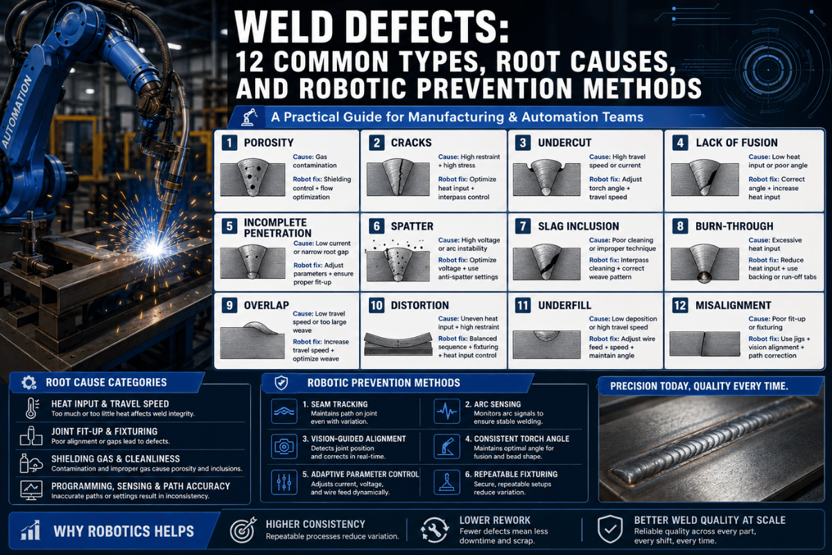
Weld Defects: 12 Common Types, Root Causes, and Robotic Prevention Methods
Contents
show
Just one weld defect on a key primary structural element can cascade into a complete section replacement. In shop fabrication and field erection, a single defect can command 5–8% of total welding hours into rework on manual processes. When an inspection escaping defect arrives “hot,” that cost doubles again.
Structured into three risk levels: practical, visually accessible for visual inspections; inspection accessible, internal and require NDT to examine; and structural, No-Tolerance rejections—under any standard.
⚠ Engineering Note: All acceptance criteria cited below are from AWS D1.1:2025 for statically loaded non-tubular connections unless otherwise specified. Cyclic, seismic, and tubular structure applications carry additional requirements. Consult the full standard and a qualified welding engineer for project-specific applications.
What Is a Weld Defect?
Hence, in terms of AWS D1.1 standards, the fact that a weld gets defected does not mean that it suffers from all possible imperfections. D1.1 defines unambiguously the difference between:
- Discontinuity: any irregularity or break in the usual form of the weld – a change in geometry, chemical composition or physical characteristics. Discontinuities are found in nearly all welds to some extent.
- Defect:A discontinuity which exceeds the acceptance criteria of the standard to which the part is subject. A typical example: every weld defect is a discontinuity, but not the other way.
While this may seem insignificant in practice, it is!A size pore on a fillet weld that is less than the aws D1.1 distribution limits still remains a discontinuity in the weld structure. If it were located on a complete joint penetration (CJP) groove weld transverse to the applied tensile stress however it would be considered a defect, requiring removal and repair.
Classification: External vs. Internal
Weld imperfections can be classified into two general types, depending on how easily they can be detected:
External (surface) defects can be seen or measured without using any special equipment: undercut, overlap, weld spatter, arc strikes, burn through and underfill. Visual inspection by a Certified Welding Inspector (CWI) is the first and most cost-effective detection method.
Internal defects – the most significant welding defect group – need to be identified by UT, RT or some other type of NDT methods: porosity, incomplete fusion, incomplete penetration, slag inclusions as well as most of weld cracks. These defects are more hazardous because they have been present in production welds passing visual inspection.
Every weld discontinuity must be evaluated against the acceptance table; a weld discontinuity below the limit stays in service, while those over the threshold require reworking. AWS D1.1 further divides welds into loading category for the fatigue structure, stiffness cyclically loaded- or slowly applied load. Steel structure fabrication for the heavy industry follows the Clause 8 visual criteria but engineered structural drawings may have additional NDT requirements.
This tabulation presents all 12 types of defects herein covered under only one of the two possible categories, sorted from the generally visually-most obvious to the most structurally-critical:
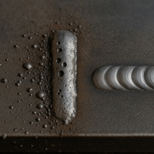
Weld Porosity — Causes, Types & Prevention
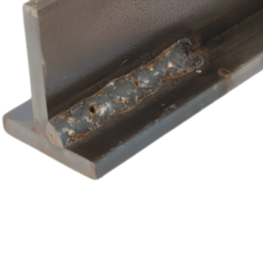
Weld porosity: the usual welding defect in MIG/GMAW welding, resulting from entrapped gases trapped when the weld pool solidifies, leaving “holes” in the weld bead (from the pinhole-dimension pores which aren’t visible to the naked eye, to the surface-visible holes which are failed by even visual inspection on sight, to the elongated wormholes which can only be seen via RT or UT inspection.
What Causes Porosity in MIG Welding?
The cause will always be the same: entrapped gas, but it may be caused by:
- Inadequate shielding gas: gas flow rate too low (target: 22-30 CFH/10-14 L/min), gas hose leaks, drafts, or a contaminated cylinder
- Dirty base material: mill scale, rust, paint, oil, and moisture on the base metal will introduce hydrogen and CO into the weld pool; grind or degrease within 2″ of the weld zone
- Excessive wire stickout: extending the wire more than 1/2″ (12 mm) out the contact tip will reduce the shielding gas envelope and cause instability in the arc
- Incorrect gun angle: excessively exceeding a 15 tilt will cause the gas cone to wander off the weld pool, letting atmospheric nitrogen and oxygen into the molten metal
- Moisture-saturated electrodes or flux: in SMAW and FCAW, wet consumables will decompose in the arc and cause pin holes in the weld
Types of Porosity
- Piping porosity (“wormhole”): elongated voids running along the axis of the weld; due to continual gas evolution from moisture on or foreign matter in the base material
- Surface porosity: visible holes in the weld face; in most structural steel, this is arejected defect unless the bubbles can be measured quantitatively, such as for water-pressured vessels or other code-referenced components.
- Distr ibuted (subsurface) porosity: spherical voids evenly distributed within the weld deposit; only detectable using RT or UT
AWS D1.1:2025 Porosity Acceptance Limits
For on-the-spot visual inspection of statically-loaded members (Table 8.1):
- Groove welds: Total visible piping porosity of 1/32 in. (1 mm) diameter shall not exceed 3/8 in. (10 mm) in any linear inch of weld, and none of more than 3/4 in. (20 mm) in any 12 in. (300 mm) section of weld
- CJP groove welds perpendicular to the direction of the calculated tensile stress: No visible porosity allowed
- Fillet welds: No visible piping porosity permitted.
Prevention
Check the gas flow meter at the beginning of each work shift. Check the gun liner and nozzle for spatter accumulation;if they are significant, it would be the most likely cause for short-term and intermittent porosity on a properly-calibrated MIG setup. For heavy mill scale on steel plates, mechanical grinding to bright metal in the weld zone is generally more reliable than chemical cleaning alone.
Undercut in Structural Welding
Undercut: a groove or channel melted into the base metal at the weld toe which is not filled with weld metal. It causes a decrease in the cross-sectional member area at one of the most stress-loaded portions: the weld toe.
What Is Acceptable Undercut in Structural Welding?
AWS D1.1:2025 shows the following acceptance criteria for undercut…
| Weld Category | Max Undercut Depth | Notes |
|---|---|---|
| Primary member — transverse to applied tensile stress | 1/32 in. (0.8 mm) | Strictest limit; fatigue critical |
| All other welds | 1/16 in. (1.6 mm) | Max for 2 in. (50 mm) cumulative length; no undercut at all in the last inch of a weld |
Causes of Undercut
- High arc voltage- excess energy causes metal to melt faster than the filler material can fill the groove
- Travel speed to fast-insufficient deposit time at the joint toe(s); the arc excavates the toe and the wire cannot keep up
- Wrong electrode angle-fillets if work angle is too steep, arc energy is directed into the bottom plate’s toe, causing an undercut in the top fillet’s toe
- Weave too wide-globular weld pools are thinnest at the distal crest, so they will be unable to fill the toe groove
Repair
Weld repair of undercut requires grinding smooth — provided the remaining throat still meets the design dimension. If grinding would reduce the effective throat below the minimum shown on the approved drawing, a butter pass to fill the groove is required before grinding flush.
Weld Cracks — The Most Dangerous Defect
Cracks have zero acceptance criteria under AWS D1.1-golol categories, all directions, any size. No weld crackmay be present without removal a repair. AWSD1.1 does not proclaim any crack worse than any other crack.
Cracks divide into two fundamentally different failure modes. A hot crack forms at an elevated temperature in the weld metal during or shortly after solidification; a cold crack will form long after the weld has cooled; up to several days later. Each must be guarded against with a different technique.
Hot Cracks vs. Cold Cracks
| Property | Hot Cracks | Cold Cracks (HIC) |
|---|---|---|
| Formation temperature | During or immediately after solidification (above 1,200°C) | After cooling below 200°C — often hours to days later |
| Root cause | Grain boundary liquation + solidification shrinkage stress | Hydrogen + residual stress + susceptible microstructure (delayed cracking) |
| Location | Weld metal centerline, crater, heat affected zone (liquation cracks) | heat affected zone (HAZ), under-bead, weld metal root |
| Primary prevention | Control heat input, filler metal composition (C/S/P limits), backfill craters | Preheat to 100–120°C, low-hydrogen electrodes (H4 or H8 designation) |
Critical: A cold crack — the result of hydrogen-induced cracking (HIC) — is uniquely dangerous because welds can pass initial inspection and crack days later. Each cold crack that forms through delayed HIC must be excavated completely before weld repair can begin. Hydrogen atoms diffuse through the weld metal after solidification; when they accumulate and recombine in microvoids, the localized pressure can exceed the material’s ductile capacity. High-restraint joints on thick structural sections are at highest risk.
Other Crack Types
- Crater crack-shallow cracks radiate from the weld crater at the point the arc was terminated. All crater cracks are rejects under AWS D1.1backfill the crater and break the arc to prevent this type of hot crack.
- Reheat cracks form in the Heat Affected Zone during PWHT or service at high temperature. They are most common in high alloy and creep resistant steels.
- Lamellar tearing-Step like fracture in the plane of the working surface of the plate, due to through-thickness tensile stress in a low Z steel grade rolled plate.
Prevention
Preheat and interpass temperature limits for structural steel welding per AWS D1.1 Clause 7 (Fabrication). The 2025 edition eased the limits for a number of joint and component shapes. As anything with less than 1 in, (25 mm) thick, internal weldments require preheating to 100–120°C (212–248°F) — sustained throughout welding — to reduce residual stress and the hydrogen diffusion rate. The interpass temperature should be maintained from preheat through quench. Specify low hydrogen electrodes (E7018 (H4R or H8) for SMAW, ER70S-6 wire for GMAW with dry cylinders and store the SMAW electrode in a 250-300F rod oven until in use. Any crack shows author fails requirements must follow the approved WPS and preheating requirements must match those of the original weld, even in repair work.
Incomplete Fusion and Incomplete Penetration
The two internal defect types are interlinked for one reason-they can be impossible to see in the visual inspection. Both are a failure of the weld metal to adhere to the adjacent metal and create a gas-tight, plane discontinuity that serves as a stress intensifier in a loaded part of the weldment.
Lack of Fusion (Incomplete Fusion)
Lack of fusion – occurs when the weld metal does not completely fuse to the base metal, and also not to the previous weld bead. This leaves a bond-line crack which is a plane void with almost zero opening, and is an excellent crack initiator.
Primary causes:
- Wrong gun angle (0-15 from vertical in fillet welds) – the arc ap plans the weld pool in front of the fusion front.
- Travel speed too fast — the pool advances before adequate sidewall fusion is achieved
- Inadequate heat input can be due to: Voltage or wire feed speed too low for the cross section of the joint
- Dirty joint preparation- oxide layers as a thermal barrier at the fusion boundary
Cold lap is a different but related defect: the weld metal overfills and rolls over the weld toe without welding to the base metal. It is caused by having the work travel too slowly, so that the weld pool overflows and becomes pushed ahead of the traveling work piece. Cold lap and lack of fusion can, and often do, occur on the same weld pass.
Incomplete Penetration
Incomplete Penetration: Indicates that the weld does not go to the depth required in the joint. For a CJP (complete joint penetration) weld the incomplete penetration would be considered a defect. For a PJP weld the required throat would have to be in accordance with the design dimension.
Reasons: Root opening is too tight, lack of heat input with regard to the thickness of the plate, travel speed is too high at the root passes or incorrect electrode/wire size for the joint geometry
Detection
Both are inspection penetration types and are detected reliably with either UT or RT. While using UT is common with structural steel, it can detect all planar flaws, which are flaws parallel to the beam, whereas RT fails to find tight lack of fusion flaws because they do not give any change in density on film. When in doubt, both are complementary.
Full comparison, with our weld testing methods guide.
Surface Defects — Spatter, Arc Strikes, Overlap, Burn-Through
Surface defects may be merely cosmetic or may be structural depending on the application. The following table summarizes the four most prevalent surface defects, their structural importance and repair requirements under AWS D1.1:
| Defect | Primary Cause | Structural Risk | AWS D1.1 Treatment |
|---|---|---|---|
| Weld spatter | Insufficient shielding gas, dirty base metal, high voltage, excessive stickout | Low — cosmetic unless concealing a surface defect | Remove when required for subsequent NDT or painting; no hard size limit in most conditions |
| Arc strike | Accidental arc contact outside the weld zone | High — creates a localized hardened zone in the HAZ that can initiate fatigue cracks | Repair required in primary structural members; grind smooth and verify with MT or PT |
| Burn through | Excessive heat input; thin base metal (<1/8 in. / 3 mm) | High — complete penetration through base metal, loss of cross-section | Repair by backwelding from the back face; reduce heat input for subsequent passes |
| Underfill | Travel speed too fast; insufficient deposit per pass | Moderate — reduces effective weld throat below design dimension | Additional weld pass required to restore minimum throat or face dimension |
| Weld overlap | Travel speed too low; weld pool rolls over toes without fusion | Moderate — unfused overlap creates a notch at the toe under tensile loading | Remove by grinding; re-weld toe if fusion is not present |
Arc strikes on base metal are particularly significant in structural fabrication. The arch strike heats the steel rapidly and then rapidly quenches it hardening the steel hardening of the surface via a martensite transformation and establishing a hard, brittle layer that are attacked by the cyclic loading of bridge girders, crane rails, and structural frames. Should an arc strike be located on a primary member then all must be repaired under AWS D1.1 grinding should normally address the hardened region completely removing the hardened region then the section is within dimensional tolerances.
Learn about managing the quality of welding in a structural steel fabricator.
AWS D1.1:2025 Acceptance Criteria — Quick Reference
Visual inspection acceptance criteria for non-tubular, statically loaded structural steel connections are summarized below for AWS D1.1/D1.1M:2025, the latest edition of the Structural Welding Code – Steel published in May 2025.
This is intended as a field reference for welding inspectors and QA engineers. Always confirm with the official standard for a project specific application, cyclically loaded, seismic, tubular structures will have additional requirements.
| Defect Type | AWS D1.1:2025 Limit (Visual) | Applies To | Note |
|---|---|---|---|
| Cracks | Zero tolerance — not permitted | All weld types | No exception by size or location |
| Porosity (groove weld) | Sum of pores ≥1/32 in.: ≤3/8 in. per linear inch; ≤3/4 in. per 12 in. length | Groove welds, static loading | Per Table 8.1 |
| Porosity (CJP, tensile transverse) | None permitted | CJP groove welds transverse to tensile stress | Strict category |
| Porosity (fillet weld) | No visible piping porosity | Fillet welds | Scattered subsurface may be acceptable per RT criteria |
| Undercut (primary member, transverse to tension) | ≤1/32 in. (0.8 mm) | Primary tension members | Fatigue-critical limit |
| Undercut (other locations) | ≤1/16 in. (1.6 mm) | Secondary members, non-critical toes | Max cumulative length applies |
| Incomplete fusion | Not acceptable | All weld types | UT or RT required for detection |
| Arc strikes (base metal) | Repair required | Primary structural members | Grind smooth; verify MT/PT |
| Weld spatter | Remove when required for NDT access | All welds | No explicit size limit in static applications |
What Changed in AWS D1.1:2025?
While several changes to the 2025 edition (23 rd edition) impact fabrication practice directly, these are especially noteworthy.
- The formally incorporated Subclause 4.7 (LRFD) – Load and Resistance Factor Design- provides a Table 4.3 of available strength values for welded joints; engineers working in the LRFD methodology now have direct code compliance support
- Expanded MT and PT provisions- new clauses provide inspection requirements, personnel qualification, and procedure documentation information for magnetic particle and penetrant testing
- Toughness requirements- additional clauses provide Charpy V-notch (CVN) toughness criteria for weld metal and HAZ
- AWS A5.36 filler metal classifications removal throughout the standard (flux-cored electrode system)
- New Annex S- addresses addition of new base materials to AWS D1.1/D1.1M
See our AWS welding standards overview for each clause-by-clause comparison between 2020 and 2025 editions. The full standard can be purchased from the ANSI Webstore or the American Welding Society directly.
Cross-reference note: ISO 5817- Welding: Fusion-welded joints- Quality levels for imperfections (Levels B, C, D)- is widely referenced for European structural use and provides broadly equivalent quality classifications. ISO 3834- governs quality requirements for the fusion welding process per se. International supply chain projects may require compliance with both AWS D1.1 and ISO 5817 simultaneously.
How to Detect Weld Defects — NDT Methods
Choosing the appropriate non-destructive testing (NDT) method for each welding defect depends on the defect type, the weld geometry, the base material, and the inspection standard. The matrix below maps the most common weld defects to the primary and secondary NDT methods used in structural steel weld inspection.
| Defect | Primary Method | Secondary / Confirmatory | Notes |
|---|---|---|---|
| Surface cracks, undercut, overlap | VT (Visual Testing) | MT or PT for crack confirmation | First inspection step; CWI qualification required |
| Surface and near-surface cracks in ferromagnetic steel | MT (Magnetic Particle Testing) | PT for non-mag materials | New MT provisions in AWS D1.1:2025; detects cracks up to 1/4 in. depth |
| Surface-breaking defects, arc strikes (non-magnetic steel) | PT (Liquid Penetrant Testing) | MT if material is ferromagnetic | New PT provisions in D1.1:2025 |
| Incomplete fusion, incomplete penetration, internal cracks | UT (Ultrasonic Testing) | RT for volumetric confirmation | Best for planar defects; PAUT (Annex H) preferred for thick sections ≥5/8 in. |
| Porosity, slag inclusion, root defects, incomplete penetration | RT (Radiographic Testing) | UT for tight planar defects | Creates permanent film record; RT can miss tight LoF perpendicular to beam |
Manual VT vs. Automated AI Vision
Conventional visual inspection by a trained Certified Welding Inspector (CWI) detects approximately 87% of surface and near-surface defects at production throughput speed. Automated AI vision systems- more commonly being integrated into robotic welding cells- currently has detection rates of 96–99% for surface detectible defects, with a lower false positive rate as the algorithm applies a single detection threshold without the fatigue factors which can leave a human inspector blind to minor visible defects after a long shift.
The current state of the art for structural steel production weld inspection combines automated inline AI vision (for porosity, spatter, under size detection) with post-weld UT or PAUT (for internal defects).
For a complete comparison of non-destructive testing capabilities for structural welds, see our weld testing methods guide and the NDT method selection guide.
Preventing Weld Defects — Parameter Control
Most weld defects are not caused by operator inexperience alone. Parameter drift- voltage creep, wire feed speed fluctuation, gas flow degradation- is equally responsible for defect production on established welding setups. A systematic parameter checklist before and during welding prevents the majority of common defects before they form.
Engineering Note (Decision Framework): When a weld defect appears in production, use the diagnostic matrix below to identify the most probable parameter deviation. In structural steel fabrication, the fastest path to defect root cause is parameter verification — not operator replacement. The same defect pattern from multiple welders on the same setup almost always indicates a parameter or equipment issue.
Defect Diagnostic Matrix
| Defect | Most Probable Root Cause | Parameter Adjustment | Verification Check |
|---|---|---|---|
| Porosity | Shielding gas loss or contamination | Check flow 22–30 CFH; clean nozzle; reduce stickout to ≤1/2 in. | Verify gas at nozzle face with flow meter |
| Undercut | Arc voltage too high; travel speed too fast | Reduce voltage 1–2V; reduce travel speed; correct electrode angle | Measure undercut depth with weld gauge |
| Lack of fusion / cold lap | Insufficient heat; wrong gun angle | Increase voltage or WFS; maintain 0–15° gun angle; check WPS | UT examination of suspect passes |
| Cold cracks (HIC) | Hydrogen + restraint + insufficient preheat | Preheat to 100–120°C; use H4/H8 low-hydrogen electrodes; bake rods | Delay MT inspection 48 hr after welding for delayed cracking detection |
| Burn through | Excessive heat input on thin plate | Reduce voltage/WFS; increase travel speed; verify joint fit-up | Check plate thickness vs. WPS heat input range |
| Spatter | Dirty base metal; inadequate gas; high voltage | Clean weld zone; check gas flow; reduce voltage/stickout | Visual check + arc sound (smooth = correct) |
All parameter changes should be logged and approved through your Welding Procedure Specification (WPS) prior to any production welding. AWS D1.1 Clause 5 covers WPS qualification and required variable changes – any changes in parameter setpoints outside of the qualified scope would then require WPS requalification.
How Automated Welding Reduces Weld Defects
Even robotic welding does not prevent welding defects – it shifts the failure mode. In manual welding operations a defect rate of 5–8% of welds per charge is common. For a model robotic system this number is below 1%. This 1% exposure is almost entirely due to fixture alignment failures and consumables management failure, not due to any inherent quality of the welding process.
In this: they control constant – arc voltage, travel speed, wire feed speed, torch angle, which are the most significant process parameters affecting manual welding defect rates. A Boston Consulting Group study found a 25% improvement in defect rates for manufacturers that integrated robotic welding systems.
Automated Quality Control
AI vision integrated into robotic welding cells achieves 96–99% detection rates for surface and near-surface flaws – 9-12 percentage points better than trained manual visual inspection at manufacturing throughput. The improvement results from consistent decision thresholds, no fatigue – AI applies measurement standards equally on the first weld or tenth thousandth.
For structural steel applications—the design of Zhouxiang’s Intelligent Steel Structure Welding System captures the entire defect avoidance cascade: closed-loop process control to prevent pinholes and undercut, laser seam tracking to avoid lack of fusion flaw on curve and irregular surfaces, and integrated postweld inspection to catch dimensional variances before delivery to the field.
See the full automated versus manual weld quality comparison in our robotic welding versus manual welding guide or view a case example of steel structure welding automation in action.
Calculate your defect reduction ROI: Use the Zhouxiang Welding Robot ROI Calculator to model the cost impact of reducing your current defect rate against the investment in an automated system. Inputs include rework hours, NDT cost per weld, and current defect rate.
Frequently Asked Questions about Weld Defects
What are the 10 most common welding defects?
The top 10 most common weld flaws when fabricating structural steel are: (1) porosity, (2) undercut, (3) incomplete fusion, (4) cold cracking (hydrogen cracking), (5) hot cracking (solidification cracking), (6) incomplete penetration, (7) slag inclusion, (8) weld spatter (gross masking defect), (9) arc strikes, and (10) underfill. Porosity is the largest contributor to MIG / GMAW welding failures; undercut dominates structural fillet welds. Cracks – although not as prevalent – carry zero tolerance in AWS D1.1 terminology and are the most severe defect category.
Which weld defect is the most serious?
Weld cracks. AWS D1.1 has zero tolerance for cracks – they are not allowed whether small, elongated, worst case hot and cold cracks, worse case opening angles, or worst case loading position. No other defect category receives this blanket rejection. Cold cracks – hydrogen glasses -present the second most severe category of failure.
What is the difference between a weld defect and a weld discontinuity?
All welds will have discontinuities – locations or features of physical discontinuities or variable property values which deviate from the normally expected condition of a weld. discontinuity, by itself, is not a failure or flaw; only if the discontinuity exceeds the limits specified as acceptable by the applicable standard will it be considered a flaw. Per AWS D1.1:2025, a porosity in a fillet weld within the tables for acceptable porosity content is a serviceable discontinuity; the same porosity level in a CJP longitudinal joint in tension is a flaw that should be removed and replaced. This distinction can have a direct impact on production, rework, and downstream costs.
Can you weld over a weld defect?
No, you can’t just place a weld over a weld defect. It is necessary to remove the defective weld metal by grinding, gouging (arc air or plasma), or mechanical means down to sound metal. The excavated region is then re-welded in accordance with the approved WPS.
Welding over a defect encapsulates the original flaw, leaving it underneath the new deposit. Cracks in particular must be fully ground out. This means the crack and any surrounding heat affected material.
How do you fix porosity in welding?
Porosity elimination is comprised of two simple steps: (1) physically removing the infected weld metal by grinding or arc-air gouging to good quality metal and re-welding; (2) correcting the root cause of the problem to take place again. Most cases of MIG welding porosity are traced back to a problem with the shielding gas flow, so confirm the flow rate between 22-30 CFH. Also check the nozzle for spatter blocking it, hose leaks, and draft blocks in the welding area.
If these have been eliminated as a cause, look into base metal cleanliness and the length of wire stickout (limited to ½ inch from the face of the nozzle). If subsurface porosity continues to be an problem, consider the possibility of a wire spool contaminated with dirt, or a base metal that is moist and requires pre-heating.
Summary
Weld defects in structural steel are predictable, and in most circumstances controllable through parameters, correct joint preparations and inspection procedures. The most damaging weld defects, cold cracks, incomplete fusion and subsurface porosity, are also visible by naked eye. They are the ones requiring proactive NDT procedures before they become problematical.
Luckily AWS D1.1:2025 give us the acceptance criteria. The engineering accomplishment is the development of the process discipline to apply.
For the large volume structural steel fabricator who wants to cut the defect rate every step of the way, robotic welding systems which combine closed-loop parameter control with inline inspection can take manual defect rates of between 5 and 8% all the way down to below 1% – thereby revolutionizing the economics of structural fabrication without sacrificing compliance with structural welding standards. Contact our Zhouxiang engineering team for an assessment of your current weld quality program.