Get in Touch with Zhouxiang

Updated August 2026
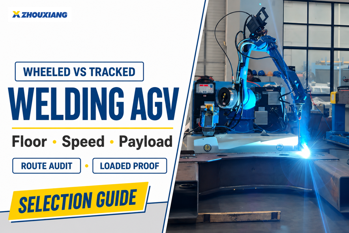
A wheeled vs tracked welding robot is a mobile chassis comparison that should be decided from the loaded route, not a vague claim that wheels are fast or tracks are rugged. Wheels normally start ahead on prepared indoor floors; tracks become defensible when measured defects, yielding surfaces, traction limits, or clearance demands defeat the offered wheeled chassis.
Scope before standards: classify the platform as autonomous or driverless, remotely controlled, or mechanically guided. ISO 3691-4:2023 covers driverless industrial trucks, but its public scope excludes rail- or guide-only trucks and remotely controlled trucks. Control mode changes which safety language can be applied.
This guide gives plant and welding teams a route audit, a mass-and-location ledger, a cycle-time calculation, and a bounded acceptance test. Readers who need category definitions, process options, or ROI should use the existing guide to mobile welding robot types and economics; exact models, configurations, prices, and quotations remain on the commercial page.
Process boundary: Chassis choice does not select among MIG welding, gas metal arc welding, submerged arc welding, laser welding, spot welding, or other automated welding processes. Each robotic arc welding, automatic welding, or adaptive welding project still needs its own welding procedures, control of welding parameters, welding quality checks, welding technologies, and utilities; claims compared to manual welding belong in a separate process study. Here, the robotic welding process and robot welding process are declared inputs, while the route audit asks whether the base can support the planned welding operation.
Wheeled vs Tracked Welding Robots at a Glance
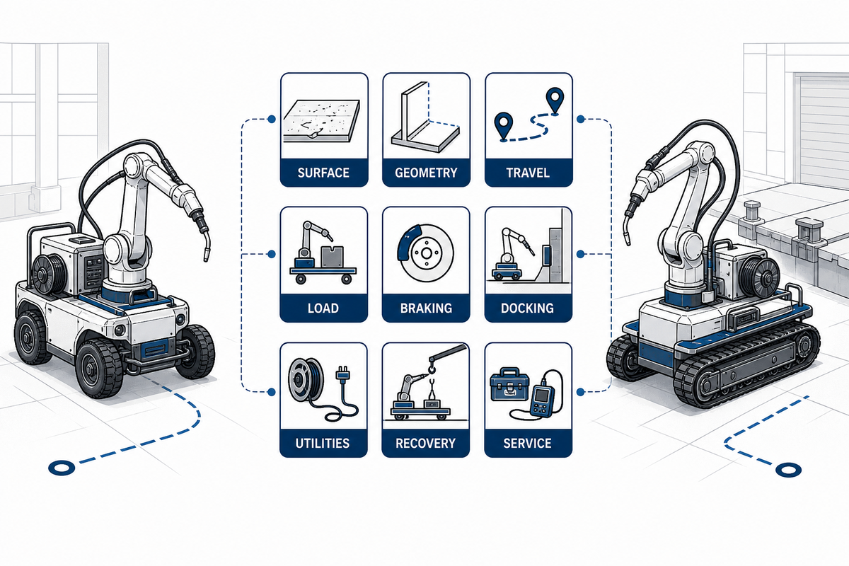
Prepared, continuous, clean routes with predictable geometry give wheeled platforms the stronger starting case. Tracked platforms earn consideration when measured discontinuities, loose surfaces, outdoor transitions, or other conditions exceed the offered wheels, clearance, braking, or steering limits. Labels such as wheeled robot platform, tracked robot platform, or AGV mobile robot don’t change the evidence required.
| Route evidence | Wheeled starting case | Tracked starting case | What still needs proof |
|---|---|---|---|
| Surface | Prepared, continuous floor | Measured loose or broken segments | Loaded passability and stopping |
| Geometry | Tight maneuvering with verified steering | Off-route access with verified skid-steer envelope | Swept path and floor interaction |
| Travel | Frequent relocations on clear routes | Traction dominates nominal speed | Full relocation cycle |
| Load | Within the complete offered envelope | Within the complete offered envelope | Mass, center of gravity, braking, and weld pose |
| Braking | Predictable contact on the surveyed route | Verified traction on limiting segments | Loaded stop, hold, and restart |
| Docking | Steered approach clears the work area | Turning envelope clears the work area | Repeated pose measurement at the weld |
| Utilities | Cable or battery arrangement follows the route | Cable or battery arrangement follows the route | Power, gas, cooling, and sweep test |
| Recovery | Access and tow plan fit the aisle | Access and recovery plan fit the terrain | Witnessed fault and restart procedure |
| Service | Wheel, tire, bearing, and steering work is documented | Track, roller, tension, and debris work is documented | Tasks, spares, access, and response ownership |
Neither column is an approval. Chassis labels can’t prove obstacle clearance, docking, stability, stopping, weld quality, or compliance for the delivered system.
Audit the Floor Before You Choose the Chassis
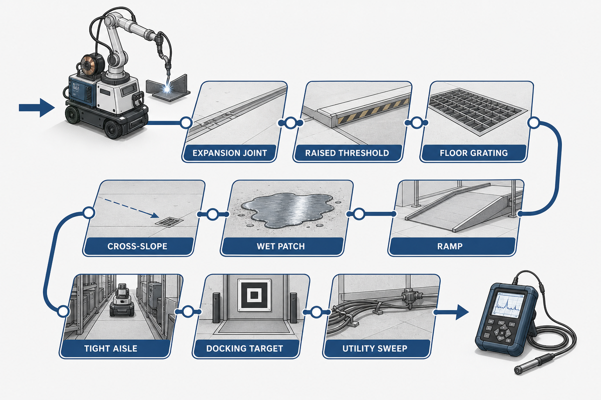
Useful floor audits record the worst condition on every production route and the direction in which the loaded platform meets it. This is the route evidence that the comparison table can’t supply. Measure joints, steps, grating, thresholds, slopes, cross-slopes, debris, wet areas, and outdoor transitions; don’t replace those observations with a universal millimeter cutoff.
ISO 3691-4 says operating-zone condition significantly affects driverless-truck safety. That supports a site survey, but the standard’s public page supplies no wheel or track passability limit for a specific machine. Suppliers must declare limits for the offered configuration, and the acceptance test must reproduce the buyer’s measured route.
| Route segment | Illustrative record | Possible failure | Acceptance evidence |
|---|---|---|---|
| Expansion joint | 18 mm wide; 8 mm deep | Wheel drop or edge strike | Loaded crossing in both directions |
| Raised threshold | 22 mm high; 80 mm approach | Belly or track-edge contact | Low-speed approach and restart |
| Floor grating | 25 mm by 60 mm openings | Contact loss or tread damage | Worst wheel or track placement |
| Ramp | 3.5° over 6 m | Traction or braking loss | Loaded stop and restart |
| Cross-slope | 2° over 4 m | Lateral stability or path error | Both travel directions |
| Wet patch | 12 m long; 1.5° grade | Slip and longer stop | Controlled stop under declared condition |
| Tight aisle | 2,450 mm clear; 90° turn | Swept-path collision | Full geometry overlay and trial |
| Docking target | ±5 mm; ±0.5° | Pose error at the weld | Repeated instrumented approaches |
| Utility sweep | 15 m cable; 12 m gas hose | Snag, tension, or abrasion | Observed routing at limiting turn |
For a route-specific example, see shipyard AGV welding applications. Use that deployment context to identify questions, not to copy limits into a different plant; the hypothetical Reference Shift used below is a time calculation and supplies no floor limit.
Measure Route Geometry and Docking Space
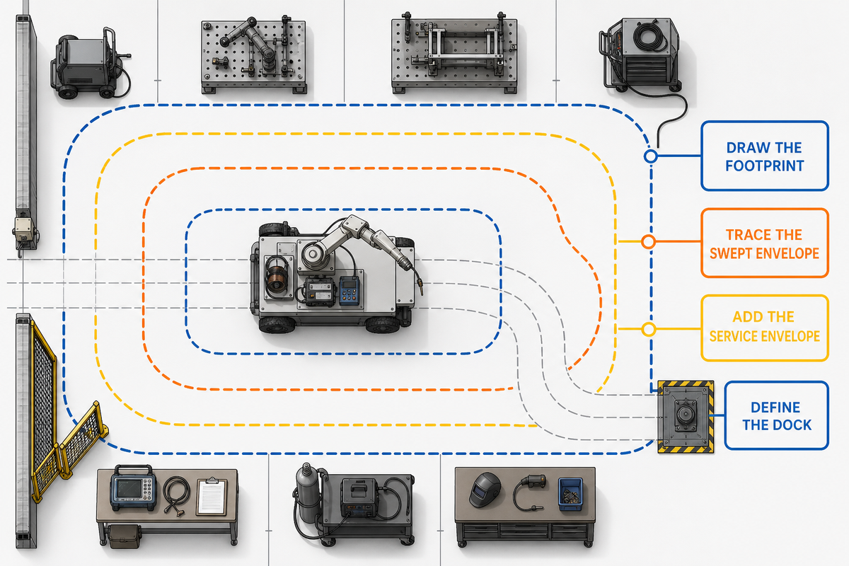
Route geometry must include the chassis footprint, its swept path through the tightest maneuver, and the service and safety envelope around it. Once the floor defects are mapped, the same route record must add this geometry. Straight-aisle width alone misses skid-steer sweep, cable or hoseline movement, recovery access, approach angle, and the accuracy needed at the welding station.
Peer-reviewed mobile welding robot research from 2025 relates configuration choices to the curve of the path and the load capacity needed. The prototype dimensions aren’t invariant aisle boundaries; the general lesson to be carried over is to consider geometry and load in unison for the machine under consideration.
- Draw the footprint: use the delivered chassis dimensions and all protrusions.
- Trace the swept envelope: include steering or skid-steer behavior at the limiting turn.
- Add the service envelope: show cables, hoses, guarding, people, and recovery equipment.
- Define the dock: state target pose, allowed translation and rotation, and the measurement method.
NIST reports completed test methods for weighted driving and docking, driving and docking on ramps, and load stability. For this acceptance plan, record repeated approaches, the localization state, achieved pose, test-instrument resolution, and measurement uncertainty. Completing the route once doesn’t prove repeatable positioning at the weld.
Convert Travel Speed into the Transit-to-Arc Ratio
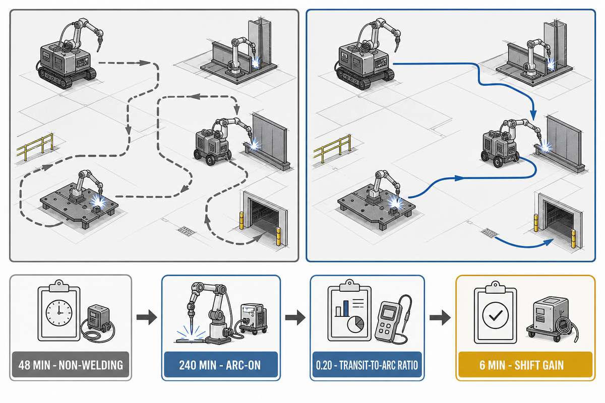
For automated welding, meaningful speed analysis asks how many non-welding minutes the mobile system needs per productive arc-on minute. The Transit-to-Arc Ratio divides travel, braking, docking, alignment, scanning, utility handling, and recovery time by productive arc-on time for the same shift.
Worked example — Reference Shift: six relocations at 8 min each create 48 min of non-welding time. With 240 min of arc-on time, the ratio is 48 ÷ 240 = 0.20. If another proposal saves 1 min per relocation, its ratio becomes 42 ÷ 240 = 0.175. That shift gains 6 min, not the difference between brochure top speeds. For spreadsheet entry, the corresponding values are 0.133 hours per relocation, 0.8 hours of non-welding time, 4 hours of arc-on time, 0.0167 hours saved per relocation, 0.7 hours of revised non-welding time, and 0.1 hours gained.
Use the same route, installed load, station count, acceleration limits, obstacle delays, docking method, scan routine, and utility arrangement for both proposals. On a short route, top-speed differences may have little effect because alignment dominates. Across many long moves, travel may become material. This ratio exposes which case you actually have.
Key takeaway
Compare complete relocation minutes per shift, not maximum chassis speed. Faster bases create value only when route time is a meaningful part of the arc-on schedule.
Replace One Payload Number with a Loaded Stability Ledger
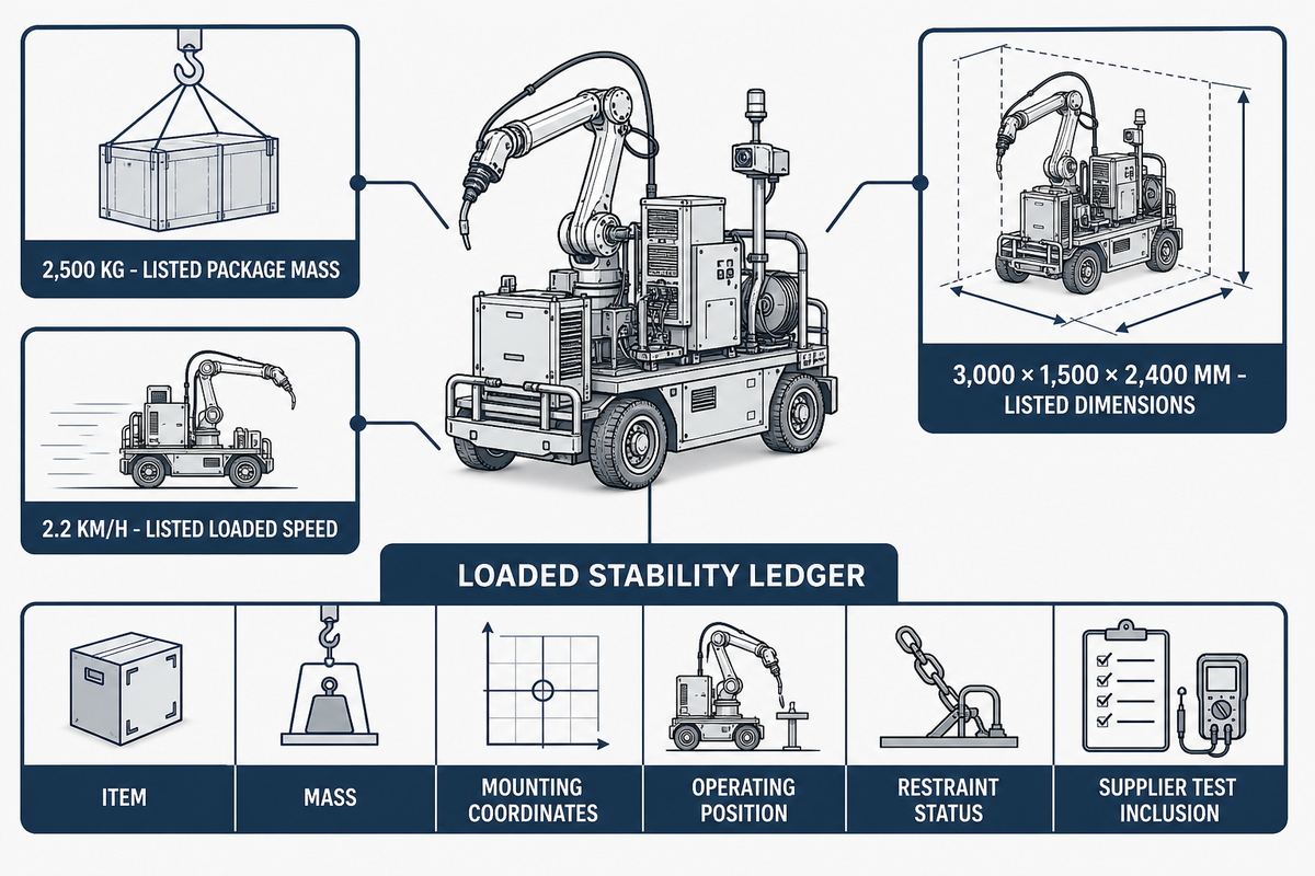
Payload capacity is only one entry in a mobile welding system’s stability case. The Reference Shift cycle-time evidence must therefore be paired with the load state that produced it. Decision evidence needs every installed mass, its mounting coordinates, the robot’s limiting pose, restrained and moving items, slope and braking cases, and confirmation that the vendor tested the same configuration.
NIST Technical Note 1955 reports that high, cantilevered loading can destabilize a mobile manipulator during navigation and contribute to off-path travel. That mechanism applies to both wheel and track proposals: distributed contact may help on yielding ground, but it doesn’t prove tip resistance, braking, floor loading, or a stable welding pose.
“Results show that cantilevered loads near the payload top height cause vehicle instability during navigation.”
2,500 kglisted standard-package mass
3,000 × 1,500 × 2,400 mmlisted package dimensions
2.2 km/hlisted loaded travel speed
These Zhouxiang figures illustrate why the complete package matters; they aren’t market ranges. Build a Loaded Stability Ledger with item, mass, mounting coordinates, operating position, restraint status, and inclusion in the supplier’s test. Ask the vendor to update it after any arm, power source, wire package, enclosure, tooling, battery, cable system, or accessory change.
Keep Transit Performance Separate from Weld Stability
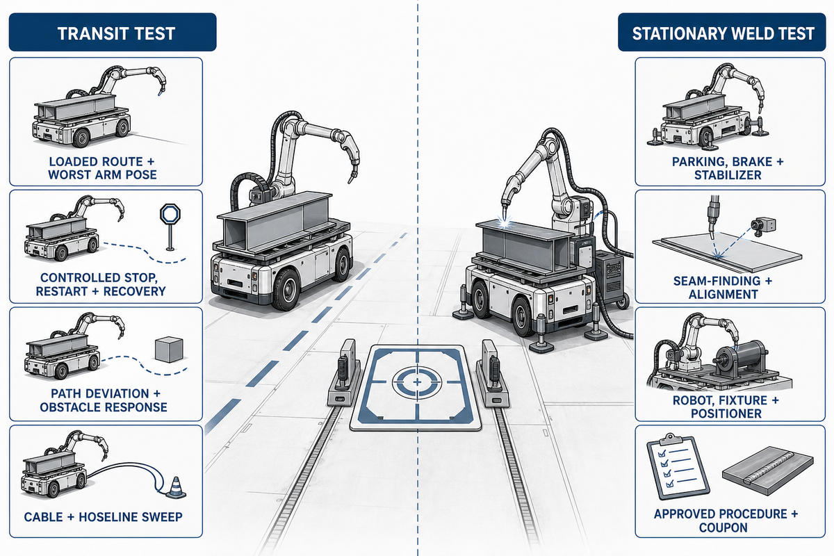
Smooth travel doesn’t prove a repeatable weld, and a sound stationary weld doesn’t prove safe travel. Robotic welding system acceptance needs two observation sets: loaded motion through the route and welding after the platform has reached its defined parked, braked, stabilized, and aligned state. Repeated docking must also place the weld seam inside the declared alignment and process window.
Transit test
- Loaded route and worst arm transport pose
- Controlled stop, restart, and recovery
- Path deviation and obstacle response
- Cable and hoseline sweep
Stationary weld test
- Parking, brake, and stabilizer state
- Seam-finding and alignment repeatability
- Robot, fixture, and positioner condition
- Approved procedure and coupon criteria
If the weld result changes, investigate the whole application: arm stiffness, torch, fixture, workpiece, positioner, seam tracking, process parameters, utility stability, and procedure. Assigning every variation to wheels or tracks produces a simple story but a poor diagnosis.
Compare Maintenance by Route Contaminants and Wear
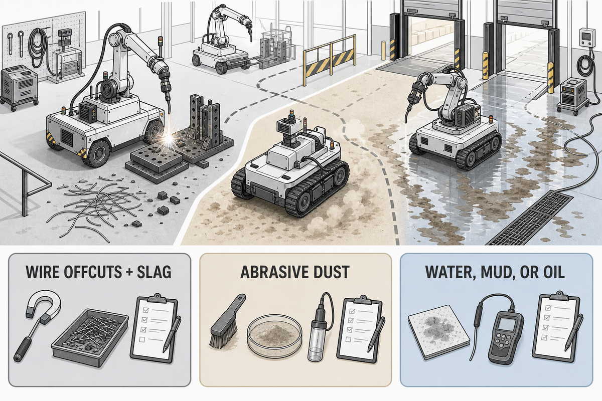
Compare maintenance against the contaminants, access constraints, duty cycle, recovery plan, and documented service tasks for each offered chassis. Tracked bases may add tension, roller, edge, and debris-removal work; wheeled bases may expose tires, bearings, steering parts, and small contact patches to different damage.
| Exposure | Inspect | Record |
|---|---|---|
| Wire offcuts and slag | Tread, rollers, guards, seals, sensors | Removal time and damage trigger |
| Abrasive dust | Bearings, tension system, drive interfaces | Inspection interval from manual and duty |
| Water, mud, or oil | Traction surfaces, enclosures, connectors | Cleaning method and return-to-service test |
What maintenance does a robotic welding station require?
Separate the base, robot and welding package, sensors, and safety functions. Obtain task intervals from the offered manuals and declared duty cycle, then price access time, tools, consumables, spares, fault recovery, and towing. Don’t publish a universal service interval where the manufacturer hasn’t supplied one.
Use the Route Reality Scorecard to Choose
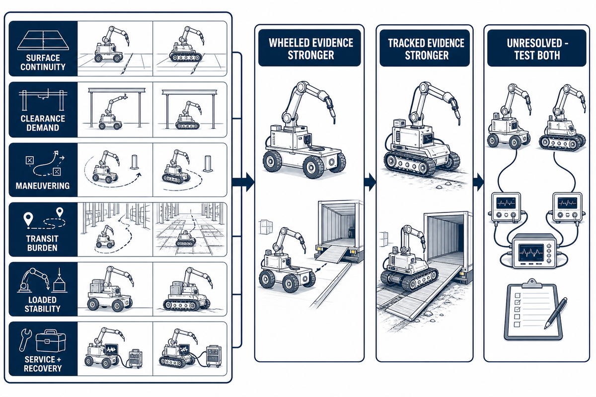
Route Reality Scorecard converts site observations into three defensible outcomes: wheeled evidence is stronger, tracked evidence is stronger, or both remain unresolved and must be tested. Maintenance findings enter the scorecard as service and recovery evidence. It deliberately avoids numeric weighting because no cited source validates a universal score across plants, loads, controls, and chassis designs.
| Evidence row | Wheeled evidence stronger when | Tracked evidence stronger when | Unresolved when |
|---|---|---|---|
| Surface continuity | Offered wheels pass every measured segment | Offered tracks pass segments wheels cannot | Limits or tests are missing |
| Clearance demand | Wheel and belly clearance are verified | Track geometry is verified against defects | Only generic labels are supplied |
| Maneuvering | Steering envelope clears the tightest approach | Tracked turning envelope clears it | Swept paths are absent |
| Transit burden | Measured cycle time is lower | Traction removes route delays | Top speed is the only input |
| Loaded stability | Delivered configuration passes | Delivered configuration passes | A payload rating substitutes for evidence |
| Service and recovery | Tasks, spares, access, and recovery fit operations | Tasks, spares, access, and recovery fit operations | Downtime work is undocumented |
After collecting these measurements, use them to compare available chassis configurations. Then send the same evidence to the supplier when reviewing AGV mobile welding robot configurations.
Copy the following fields into the RFQ. “Recommended range” means the buyer’s measured requirement plus the supplier’s declared acceptance boundary, not a number invented by this article.
RFQ checklist — copy these into your quote request:
| Parameter | Recommended range | Why it matters | How to verify |
|---|---|---|---|
| Joint, step, and grate | Buyer-measured maximum in mm | Defines contact and clearance demand | Loaded representative crossing |
| Slope and cross-slope | Buyer-measured maximum in % or degrees | Affects traction, braking, and stability | Stop and restart at limiting segment |
| Route envelope | Minimum clear width in mm | Tests the real swept path | Overlay delivered geometry on route |
| Installed load | Complete mass in kg and coordinates in mm | Exposes center-of-gravity effects | Signed Loaded Stability Ledger |
| Docking | Tolerance in mm and degrees; repeat count stated | Separates positioning from route completion | Instrumented repeated approaches |
| Utilities | Rated V/A, gas and cooling flow, cable and hose lengths | Prevents route success from hiding service limits | Drawings, nameplates, and functional test |
Run the Loaded-Route Proof Test Before Acceptance
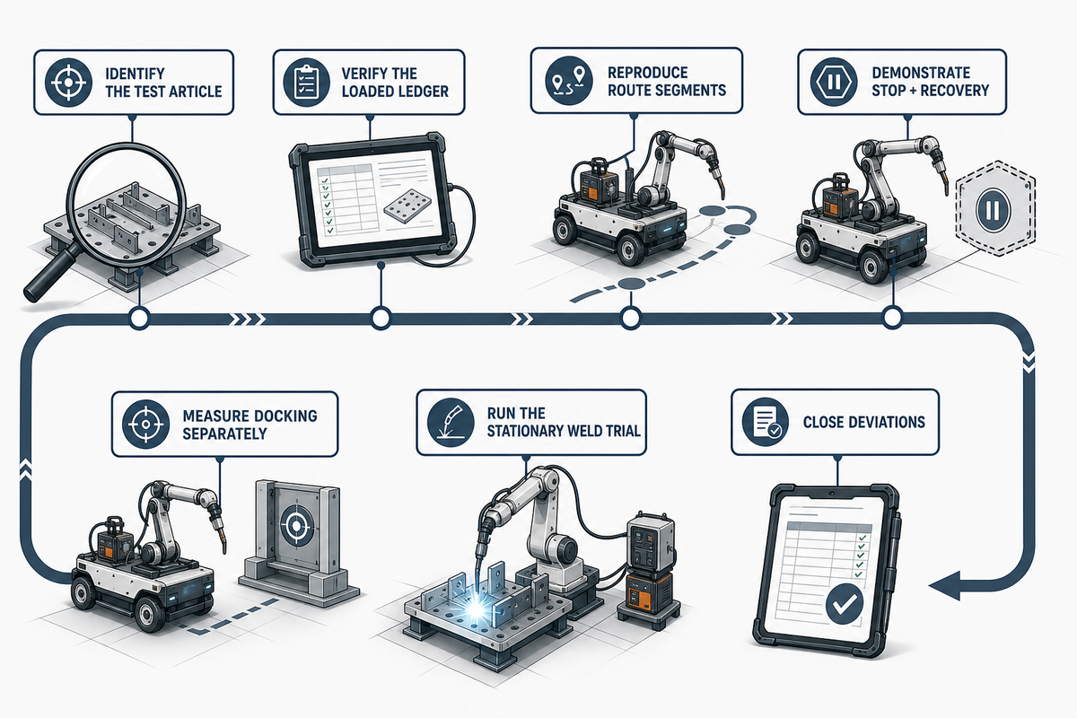
Loaded-Route Proof Test should use the actual undercarriage, software state, robot arm, welding package, cable or battery arrangement, tooling, enclosures, and accessories. The scorecard’s unresolved rows become the test plan. It’s a witnessed test of a declared configuration on representative route segments, not proof that every system function or hazard has been validated.
Configuration declaration: Across the welding industry, including steel structure work, identify the control system, robotic arm, welding torch, vision system, sensor technologies, weld paths, working environment, and every safety function governing movement of the robot. Record how automated systems guide the robot, how the influence of welding parameters is checked, and how the machine will perform welding tasks while parked. Neither an arc welding robot, intelligent welding robot, industrial welding robots, collaborative robots, nor industrial robot welding cells prove consistent weld quality; welding robot applications with multiple robots still need configuration-bound acceptance.
- Identify the test article — record chassis, software, control mode, guidance method, arm, welding equipment, and accessories.
- Verify the loaded ledger — match installed items and the limiting transport pose to the signed record.
- Reproduce route segments — cross measured defects in the relevant direction and contamination state.
- Demonstrate stop and recovery — witness controlled stopping, restart, fault response, and recovery at limiting conditions.
- Measure docking separately — repeat approaches and retain pose, localization, instrument, and uncertainty records.
- Run the stationary weld trial — isolate the base state and apply the approved welding and coupon criteria.
- Close deviations — document corrective action and repeat every failed or affected step.
Keep a separate welding-utility record for the welding machine and related welding automation equipment used in fabrication. OSHA’s arc-welding rule addresses work-lead circuits, machine-frame grounding, supply connections, conductors, cable condition, and cooling-water or shielding-gas leaks. Crossing the floor doesn’t prove the welding-current return path, protective grounding, power, gas, cooling, or cable and hoseline condition.
Standards boundary: ISO 10218-2:2025 addresses industrial robot application integration but its public scope excludes mobility hazards when manipulators are integrated with driverless trucks or mobile platforms. Qualified integrators must determine the applicable standards, regulatory duties, and risk-assessment scope for the combined application. No single citation here proves conformity.
Use the dedicated guide for the broader mobile robot safety requirements. This chassis guide keeps its narrower job: making route, load, docking, utility, and acceptance evidence visible before purchase.
Why 2025–2026 Deployments Raise the Validation Bar
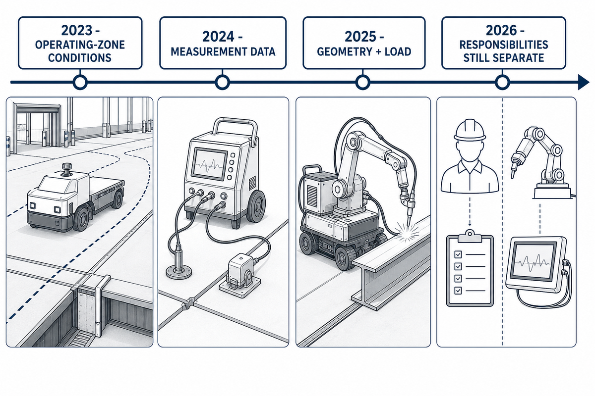
Current evidence raises the validation standard because mobile welding is expanding into more diverse routes and combined robot-platform jobs. The significant trend isn’t a market-growth rate; it’s the expanding gulf between a brochure chassis label and the test results required for a working application.
2023: ISO 3691-4 publishes its second edition for driverless industrial trucks and emphasizes operating-zone conditions.
2024: NIST publishes continuous mobile-manipulator measurement data focused on registration, repeatability, accuracy, and uncertainty.
2025: Peer-reviewed mobile welding research connects configuration choices with working-condition geometry and load.
2026: Active standards still separate mobile-robot, industrial-robot application, and welding-process responsibilities.
Tracked deployments in unstructured settings are useful examples, not proof that tracks win in a prepared plant. Likewise, a wheeled platform’s listed speed doesn’t establish shift output. Buyers should demand configuration-bound measurements and retain them as acceptance evidence.
Frequently Asked Questions
Q: What are the downsides of robotic welding?
Robotic welding adds route, integration, maintenance, safeguarding, programming, and acceptance work; a torch or chassis specification cannot resolve those duties without a documented system plan.
For a mobile system, the main selection risks are a route that the loaded chassis cannot repeat, utilities that cannot travel or dock safely, poor recovery access, unmeasured positioning error, and an acceptance plan that tests an unloaded demonstrator. Programming, fixtures, seam sensing, consumables, operator training, and change control also remain part of the delivered application. These are project-scope risks, not proof that automation is unsuitable; they are reasons to define ownership and evidence before purchase.
Q: Who makes the best robotic welder?
Best-fit suppliers offer configurations that pass your route, load, docking, welding, utility, support, and acceptance requirements, then document the limits, service responsibilities, and witnessed results.
Brand reputation cannot substitute for a like-for-like test under load. Compare the delivered chassis, robot, welding package, controls, documentation, service response, spare-parts route, and signed acceptance evidence. Prefer a supplier that discloses limits, states who owns integration work, and proposes a witnessed test using your measured route and production-equivalent load.
Q: Which robot is commonly used in welding?
Industrial articulated robot arms are common in welding, but a mobile application adds a separate base, route, docking, and integration problem that must be validated as one delivered application.
Arm type alone does not answer the wheeled-versus-tracked question. Treat the manipulator, torch, seam sensing, power source, wire and gas equipment, workpiece, fixture, safety functions, and mobile base as one offered application. Confirm payload and reach in the limiting pose, define how the base is parked or stabilized, and keep route performance separate from welding performance. Other robot forms may suit specialized work, but the selection still follows the task and integration evidence.
Q: Are tracks always better for a heavy welding robot?
Tracks are not automatically better for a heavy welding robot because mass does not reveal center of gravity, floor loading, braking, turning, or maintenance under load.
Put every installed item and its location in the Loaded Stability Ledger. Wheeled bases may remain preferable on prepared indoor floors, while tracks may help on a verified yielding surface. Delivered configurations must still pass the route and stationary tests.
Q: Can a wheeled welding AGV cross floor joints and grating?
Wheeled welding AGVs may cross joints and grating only when the offered wheel, clearance, load, and approach geometry are verified against measured route segments under load.
Record opening width, depth, step profile, direction, and the worst loaded wheel position. Obtain the supplier’s declared wheel diameter, contact geometry, clearance, approach limits, and approved load state, then reproduce the segment during acceptance. Test both directions if the profile is asymmetric. If either the site measurement or machine limit is missing, mark the segment test-required rather than assuming failure or success.
Q: What should be demonstrated before factory acceptance?
Factory acceptance should demonstrate the declared production-equivalent configuration against documented route, docking, stopping, recovery, utility, safety-function, and stationary weld criteria for the offered machine and software state.
Witness the limiting route segments, controlled stops, restart, repeated docking, fault recovery, and the approved weld trial. Retain chassis and software identity, control mode, guidance method, the loaded ledger, measurement instrument, uncertainty, results, deviations, corrective action, and retests. Confirm the welding-current return, grounding, power, shielding gas, cooling, cable routing, and service connections in their accepted state. Assign an owner and acceptance criterion to every open item, and prevent shipment or site sign-off from silently closing a failed test. A smooth unloaded demonstration on a clean floor is orientation, not a completed Loaded-Route Proof Test, and the route test itself is not complete system conformity evidence.
How This Chassis Guide Was Built
The chassis-guide analysis separates driverless-truck scope, mobile-manipulator measurement, welding utilities, and first-party configuration data so that no single source is asked to prove more than it can. The route audit, Transit-to-Arc Ratio, Loaded Stability Ledger, Route Reality Scorecard, and Loaded-Route Proof Test are decision aids, not standards or conformity certificates. Learn more about the Zhouxiang engineering background.
References & Sources
- ISO 3691-4:2023, Driverless Industrial Trucks International Organization for Standardization
- ISO 10218-2:2025, Industrial Robot Applications and Cells International Organization for Standardization
- Mobile Manipulator Stability Measurements National Institute of Standards and Technology
- Mobility Performance of Robotic Systems National Institute of Standards and Technology
- Continuous Mobile Manipulator Performance Measurement Data National Institute of Standards and Technology
- 29 CFR 1910.254, Arc Welding and Cutting Occupational Safety and Health Administration
- Configuration Design of Wheeled Mobile Welding Robots Machines, 2025
- Industrial Robot Standards Catalog Association for Advancing Automation