Get in Touch with Zhouxiang
Forestry machinery manufacturer Ponsse reduced their welding robot programming from ten days to one — a 10x speedup — by moving from teach pendant programming to offline programming. That number (published by OLP vendor Visual Components in 2025) embodies exactly why offline programming is the default workflow inside a gantry welding robot: a 12 m rail with hundreds of TCPs is not something a human wants to walk through with a handheld pendant. This how-to covers what offline programming for gantry welding robots is, the seven-stage workflow every OLP package uses, the gantry-specific reasons OLP matters more here than on stationary cells, real case-study numbers, an honest comparison against teach pendant programming, and a buyer’s checklist for choosing OLP software that fits your shop.
Quick Specs — Offline Programming Workflow At a Glance
| Programming Environment | PC-based virtual replica of the physical robot cell |
| Typical CAD Inputs | Tekla, SolidWorks, NX, CATIA, Creo (STEP or native) |
| Supported Robot Brands (typical) | ABB, FANUC, Yaskawa, KUKA (one OLP seat, multi-brand) |
| Workflow Stages | 7 (CAD import → cell layout → TCP generation → simulation → code gen → touch-up → production) |
| Typical Programming Speedup | 2x to 10x vs teach pendant (application dependent) |
| Initial Accuracy (Before Touch-Up) | Within ~1/4 inch (6 mm) after calibration |
| Typical Software Licence Cost | $3k–$30k/year per seat (mid-tier third-party OLP) |
What Is Offline Programming for Gantry Welding Robots?

Offline programming (OLP) is writing, testing, and validating a welding robot’s motion program on a PC inside a virtual replica of the cell — without ever stopping the physical robot. Instead, the robot continues welding its current job while engineers build the next program in simulation, export the generated code to the controller, and deploy it with a short touch-up pass.
Compared against teach pendant programming — the “online” method, where a technician stands within a safety fence jogging the arm point-by-point with a handheld control unit — OLP shifts programming off the shop floor and onto engineering workstations. That shift matters on any robot, but it matters disproportionately on a gantry welding robot, where a 12 m linear rail carries a 6-axis arm over workpieces five meters wide, generating hundreds of Tool Center Points (TCPs) per pass. Walking an operator through those points on a teach pendant simply does not scale.
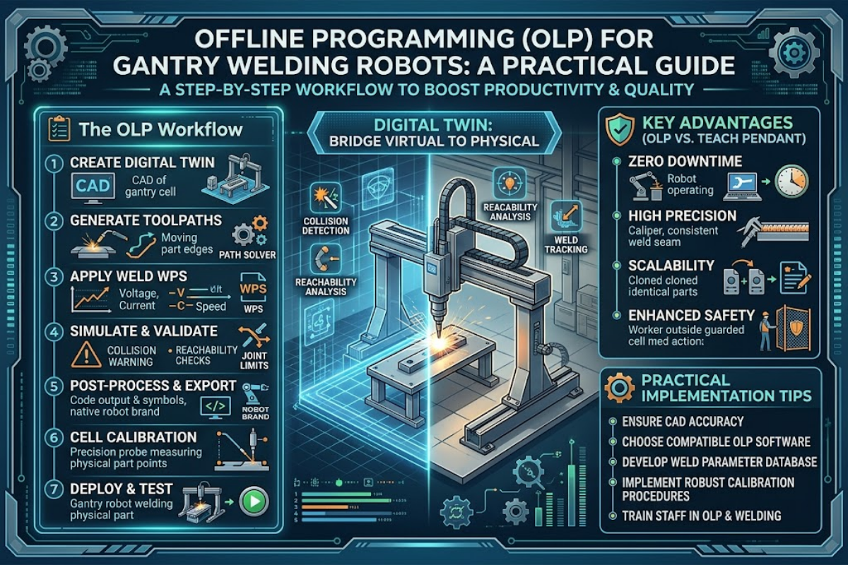
The OLP Workflow: 7 Stages Step-by-Step

Every serious OLP package for robotic welding follows broadly the same seven-stage pipeline, whether it is RoboDK, Visual Components, Robotmaster, FASTSUITE, OCTOPUZ, or an OEM-proprietary tool. Understanding these stages tells you what CAD data you need upstream and what the robot controller receives downstream.
- Import CAD data. Robot geometry comes from the OEM; workpieces from the customer’s CATIA or NX model; fixtures from SolidWorks; tooling from Creo. Files arrive through neutral formats (STEP, IGES) or native translators. Boundary Representation (B-Rep) accuracy of the imported geometry is what downstream TCP generation depends on.
- Lay out the virtual cell. Position the robot, positioners, fixtures, and workpiece in a 3D environment that mirrors the shop-floor geometry.
- Generate TCPs. Software computes Tool Center Points from surface normals and edge geometry along the intended weld seams; arc-length sampling keeps TCP spacing uniform along curved paths.
- Simulate motion with collision detection. Run the full program virtually. This solver checks for body-pair collisions, reachability failures, and singularities (joint configurations where the kinematic Jacobian loses rank and motion becomes undefined).
- Generate robot-specific code. A post-processor exports native code for the target controller — ABB RAPID, FANUC TP, Yaskawa INFORM, or KUKA KRL. Third-party OLP packages usually ship post-processors for 10–15 robot brands.
- Physical touch-up. Load the program onto the real controller. Teach the robot a handful of reference points (worktable location, rotational-axis origin, weld start) and let the software reconcile CAD-to-physical deviations. Well-calibrated programs typically land within ~1/4 inch (6 mm) of final accuracy before touch-up.
- Run production. Start the weld, monitor through the controller or MES, and iterate on the next program in parallel.
This seven-stage pattern is documented in a 2017 Procedia Manufacturing paper on an offline CAD-based robot programming cell for shipbuilding, which describes the same flow applied to a 9-degree-of-freedom system (a 6-axis robot arm mounted on a 3-axis XYZ gantry). Its authors make the case that inexperienced programmers can produce production-ready weld sequences once the CAD pipeline is in place — a core premise of modern OLP.
Why Gantry Welding Robots Need OLP More Than Stationary Cells

Stationary 6-axis robots are programmable with a teach pendant within reason: the work envelope is bounded, every joint is visible from outside the fence, and a typical weldment has tens of TCPs, not hundreds. Gantry welding robots break all three of those assumptions.
First, the rail is a true axis, not a transport step. A single controller coordinates the linear stroke with the six articulated joints during welding, which means path planning has to solve inverse kinematics across 7+ degrees of freedom. Spatial’s 2026 analysis of offline programming technology notes explicitly that gantry systems “add additional degrees of freedom beyond the robot arm… the solver has to treat the gantry axes as part of the kinematic chain” — which changes the reachable workspace and the singularity landscape compared with a fixed pedestal. Second, the physical envelope is huge: a 12 m rail with a 5 m weld span means a programmer would need to walk meters between TCPs on a teach pendant. Third, gantry cells often include a workpiece positioner as an 8th or 9th axis, and a peer-reviewed shipbuilding case describes a 9-DOF cell (6-axis arm + 3-axis gantry) explicitly designed so an “inexperienced programmer” can produce production programs.
If you have read our companion guide on the 7-axis gantry welding robot, the takeaway here follows directly: the same added axis that expands the work envelope is what makes manual teaching unworkable — and what makes a proper OLP toolchain mandatory rather than optional. For the broader mechanics, see how a gantry welding robot works and the ground rail vs cantilever vs gantry comparison.
💡 Pro Tip
OLP pays off fastest on long, continuous weld seams with many TCPs. Pure pick-and-place work with 4–5 points is still cheaper to program at the pendant. Industry association A3 (Association for Advancing Automation) notes the same threshold in their OLP primer.
Benefits Backed by Real Case Data
Making the case for OLP on a gantry welding robot is concrete work, not speculation. Several manufacturers have published verifiable programming-time cuts after adopting third-party OLP:
10x
Ponsse: 10 days → 1 day programming
70%
AMI Attachments: 2 weeks → 4 days
80%
Berlin Gardens: programming time cut
2.5x
AFRIT: daily output 8 → 20 bins
These numbers come from manufacturer case studies published by Visual Components in 2025 and reflect real-world deployments on welding lines — not projected or aggregated benchmark data. Ponsse, a Finnish forestry-machine manufacturer, reduced programming time on an ABB welding robot mounted on a three-axis gantry from ten days to one; programs were built against the 3D CAD model of each new workpiece before the controller ever saw them, which eliminated the downtime window that traditional teach-pendant workflows force. AMI Attachments, a North American heavy-equipment attachments maker, cut a typical shop-floor programming cycle from two weeks to four days. AFRIT, a South African trailer builder, doubled daily output from eight to twenty bins by eliminating manual programming as a bottleneck.
Underneath the headline numbers are three reinforcing mechanics. Programming happens in parallel with production, so the robot earns money while the next program is being written. Calibration tools (three-point transformation, multipoint best-fit, in-process probing) reconcile the virtual cell to the real cell once, and that reconciliation holds across subsequent programs. And a single third-party OLP seat can drive mixed robot fleets — software vendor OCTOPUZ ships post-processors for roughly 15 brands, so a shop running ABB, FANUC, Yaskawa, and KUKA robots programs all of them through one UI rather than four. Our robotic welding ROI calculation guide covers how this programming-time saving rolls into the overall automation payback math.
Teach Pendant vs Offline Programming: When OLP Wins

Offline programming does not replace the teach pendant entirely; every deployment still uses a pendant for the final touch-up pass. What matters is who does the bulk of the programming: a technician inside the fence, or an engineer at a desk.
| Dimension | Teach Pendant (Online) | Offline Programming |
|---|---|---|
| Production during programming | Stopped | Running in parallel |
| Time for a 100-TCP weld path | Days | Hours |
| Multi-robot-brand support | One OEM at a time (proprietary pendant per brand) | Single seat drives 10–15 brands |
| CAD integration | None (manual point-by-point) | Direct import from Tekla / SolidWorks / NX / CATIA / Creo |
| Shop best fit | Low-complexity mass production, 4–5-point jobs | High-mix low-volume, long continuous seams, gantry cells |
OLP is not universally superior. Pendant programming still wins on shops that run a single part in volume with a handful of TCPs — the A3 industry association’s OLP primer notes that pendant programming remains more cost-effective “for processes with only four or five points.” It also wins where your engineering team has no CAD workflow to feed into the software: no CAD in means no programs out. And the OLP licence itself runs roughly $3k–$30k per year per seat, which is a real line item for shops with a single robot.
A deeper method comparison lives in our broader write-up on welding robot programming methods, and the productivity trade-off against manual welding overall is covered in robotic welding vs manual welding.
Estimate the payback before you commit
Before writing a purchase order for OLP software, run the numbers against your own workpiece mix and programming-labor cost. Our welding robot ROI calculator and the workstation-level efficiency estimator let you size the programming-time saving against licence + training cost — no login required.
What’s Inside OLP Software: Five Components That Matter

OLP packages all look similar from the outside: a 3D viewport, a tree of cell components, a weld-path editor, a post-processor. Real differences live in the five layers that do the hidden work. When you are evaluating vendors, these are the components to ask about. For a broader view of the automation stack, see our overview of robotic welding technology.
CAD Translator Layer
Every robot cell involves geometry from multiple CAD systems. The translator reads native CATIA, NX, SolidWorks, Creo, Inventor, and neutral STEP files while preserving B-Rep topology, PMI (Product and Manufacturing Information), and metadata. If the translator drops surface normals or flattens edges, downstream TCP generation gets inaccurate. Fidelity at this layer is non-negotiable.
Kinematic Model of Your Gantry
Generic robot solvers can handle a 6-axis arm. A gantry cell adds the rail (7 DOF) and often a positioner (8 or 9 DOF). This solver needs a kinematic library that matches your specific rail length, arm brand, and positioner configuration — otherwise reachability and singularity analysis get unreliable at end-of-travel positions. Ask the vendor for a model file matching your exact hardware before you buy.
Collision Solver
Collision detection runs in two modes. During interactive simulation, the solver returns a fast first-contact signal to the UI. Before deployment, it runs an exhaustive pass that reports every colliding body pair and intersection point — the diagnostic the programmer needs to fix the path. On a gantry, collision scope must include the rail, carriage, cable chain, and torch relative to the workpiece and fixtures — not just arm-versus-part.
TCP Generator
Surface-normal evaluation gives the torch its approach angle at every waypoint. Arc-length parameterized sampling along edges keeps TCP spacing uniform along the physical curve geometry, rather than bunching points in high-curvature regions. For weld seams that follow an edge across multi-segment paths, the generator also needs smooth edge propagation so the resulting motion stays G1-continuous.
Robot-Specific Post-Processor
Post-processors translate the generated motion program into each controller’s native language: ABB RAPID, FANUC TP, Yaskawa INFORM, KUKA KRL. A third-party OLP that ships post-processors for 10–15 brands lets one seat drive a mixed fleet. An OEM-proprietary OLP (RobotStudio, RoboGuide, MotoSim, KUKA.Sim) is usually deeper on its own brand but will not help if you also run two other brands on the floor.
Five Checks Before Buying OLP Software for Your Gantry
Run through this list before signing a purchase order. Each item has burned at least one shop that skipped it.
- Gantry kinematic coverage. Confirm the vendor’s library has a model matching your rail length, arm brand, and positioner configuration. Generic solvers lose accuracy at end-of-rail positions; request a demo on a cell geometry that matches yours.
- CAD format coverage. Match vendor-supported imports to your engineering stack. Structural-steel shops mostly work in Tekla; shipyards run CATIA; general fab uses SolidWorks or NX. A package that only imports STEP will force a translation step and lose PMI.
- Multi-brand post-processors. Running a mixed FANUC / ABB / Yaskawa / KUKA fleet? One third-party OLP is cheaper and easier than one OEM-proprietary seat per brand. Ask for the current post-processor list before committing.
- Calibration tooling. Three-point transformation, multipoint best-fit, and in-process probing are the tools that reconcile CAD-to-physical deviations. A documented case from OLP vendor CENIT describes exactly how a Crown Equipment 13-axis cell was recovered once the integrator’s drawings diverged from the physical setup — calibration is what makes OLP work in practice, not just in theory.
- Rail-aware collision detection. Your solver must see the rail, carriage, and cable chain as obstacles — not just arm-versus-workpiece. Validate this on the demo: ask the vendor to show collision detection between the gantry carriage and a fixture mid-rail.
📐 Engineering Note — Worked ExampleA mid-volume structural-steel shop running a 12 m rail with a single FANUC arm and a Tekla model-import workflow typically lands at $8k–$15k per year for a mid-tier third-party OLP seat — plus a one-week training bill for the engineering team. Payback on the programming-time saving alone is inside 6–9 months at 1,500+ H-beams per year. Our welding robot selection guide covers the broader capex context.
Request a Zhouxiang gantry welding robot workstation quote →
Frequently Asked Questions

Q: What’s the difference between offline programming and teach pendant programming?
View Answer
Teach pendant programming (also called online programming) is done on the physical robot, with a technician inside the safety fence jogging the arm and recording waypoints one at a time. Production is stopped during the programming process. Offline programming (OLP) runs entirely on a PC using a virtual replica of the robot cell, so the physical robot can keep producing while the next program is being built. You still use the teach pendant for a short final touch-up pass to reconcile any small CAD-to-physical offsets — but the bulk of the work moves off the shop floor and onto engineering workstations.
Q: How much faster is OLP than teach pendant programming on a gantry?
View Answer
Published case studies report 2x to 10x speedups. Ponsse went from ten days to one day; AMI Attachments went from two weeks to four days.
Q: Do I need a CAD model of every fixture and workpiece?
View Answer
You need CAD for your robot (usually supplied by the OEM), your workpiece, and any fixtures the robot will move around. If you do make-to-print work with no upstream CAD, a stereo-camera point-cloud option lets you scan and weld without modeling first — but this is a paid feature and not every OLP package ships it.
Q: Will OLP work with my existing robot brand?
View Answer
Third-party OLP packages usually support 10–15 brands (ABB, FANUC, Yaskawa, KUKA, Panasonic, Kawasaki and similar). Confirm the specific controller model and firmware against the vendor’s current post-processor list before buying.
Q: Can I skip pendant touch-up entirely with OLP?
View Answer
No. OLP typically gets you within about 1/4 inch of final accuracy, which then needs a brief touch-up pass at the cell. Skipping that step usually produces weld defects from small offsets between the CAD model and the physical fixture.
Q: Is OLP worth it for a shop with just one gantry welding robot?
View Answer
If the gantry runs long continuous seams with many TCPs — H-beams, box columns, hull panels — yes, a single-seat third-party OLP generally pays back inside a year on programming-time savings alone, even without adding a second robot. If the shop runs mass production of a single simple part with few weld points, the teach pendant still wins on capex and the OLP licence is hard to justify. Shops running mixed robot brands benefit most, because one OLP seat replaces multiple OEM pendants and training programs.
Related Articles
- Robotic Welding Cell Cost Breakdown — capex and opex line items
- Welding Robot Maintenance Schedule — what to check and when
- Welding Robot Cost Breakdown — total-cost-of-ownership math
- Gantry Robot vs Articulated Robot for Welding — configuration trade-offs
References & Sources
- Offline CAD-based Robot Programming and Welding Parametrization of a Flexible and Adaptive Robotic Cell for Shipbuilding — Procedia Manufacturing (Elsevier), 2017
- Demystifying Robot Offline Programming — Association for Advancing Automation (A3)
- World Robotics 2025 Report — International Federation of Robotics
- Welding Workforce Data Portal — American Welding Society
- Off-line Programming and Simulation from CAD Drawings (arXiv) — peer-reviewed industrial application study
About This Analysis
This guide is written for fabrication engineers evaluating offline programming software for gantry welding robot cells. The case-study productivity numbers (Ponsse 10x, AMI Attachments 70%, Berlin Gardens 80%, AFRIT 2.5x output) are drawn from published manufacturer case reports; the technical workflow maps to the peer-reviewed 9-DOF shipbuilding cell study in Procedia Manufacturing. Zhouxiang’s 34 years of welding-automation deployment experience shapes the gantry-specific buying checklist, but all sourced statistics above come from independent authorities, not vendor literature.