Get in Touch with Zhouxiang

Robotic Welding Cell Layout Design: Best Practices
Poorly designed robotic welding cell layouts cost building manufacturers tens of thousands of dollars in rework, lost manufacturing time, and safety incidents that never needed to happen. Relatively few purchasing decisions you make before steel is cut or a robot is bolted to the shop floor make the difference between a cell that reliably operates at 90% uptime and a cell that limps along at 60%. This guide walks through the key considerations – robot reach, fixturing, weld sequence simulation, safety, and capital equipment costing for pre-engineered vs. custom cells – so you can get it right the first time.
What Goes Into a Robotic Welding Cell Layout?
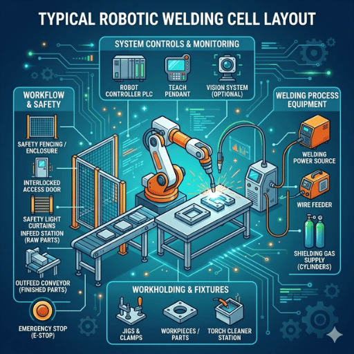
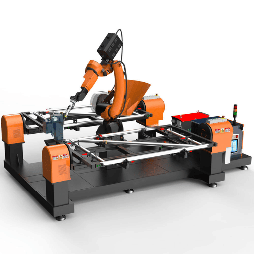
A robotic welding cell layout is the arrangement of robots, positioners, fixtures, sensors, safety barriers, and material movement paths inside a well-defined floor space designed to produce consistently welds at a target cycle time to the machine versus operator while protecting all persons from arc flash, fume exposure, and moving robot equipment. Every decision on component location impacts throughput, process capability, and operating costs.
Proper layout design begins with workflow planning. You should make a detailed map of the path each component takes starting from raw material delivery, through fixturing, welding, cooling, and package unloading. If you design a robotic weld cell that requires operators to cross the machine’s work envelope to load parts, you will ultimately see either a workplace injury or severely crippled production.
Component placement must follow workflow. Each robotic welding system needs the robot arm positioned so the reach of the robot covers all weld joints without repositioning. Each positioner sits inside that envelope. Fixtures mount to the positioner. Sensors, nozzle cleaning stations, and tool changers cluster on the non-operator side of the cell, where they remain easily accessible for maintenance yet out of the work flow path.
Floor space is dictated by material flow. Load and unload areas should be adjacent when possible since the operator should be able to drop a finished assembly without walking more than a step or two while rack up a new raw assembly.
Safety zones comprise the perimeter of a robotic welding cell layout. Light curtains, physical fencing, interlocks, and emergency stops define where people can and can’t be during the robot’s operation. These zones need to adhere to ANSI/RIA R15.06-2012, which governs industrial robot system integration in the United States (OSHA Robotics Standards).
From the 1000+ welding automation projects we have delivered, good layout decisions made during the initial design phase determine nearly 80% of a cell’s long term throughput. Moving a positioner after concrete has been poured and conduit run will cost 10X what it would cost you on paper.
Key Components Every Weld Cell Needs
Your robotic weld cell is only as effective as its weakest element. Every piece of material movement equipment must be sized, integrated, and selected to work with every other component in the cell. Here is how to determine how to choose each element for your production-ready welding robot cell.
| Component | Function | Selection Criteria |
|---|---|---|
| Robotic Arm (6-axis) | Moves the welding torch through programmed weld paths | Reach 650–3,000 mm, payload from a few kg up to 1,000+ kg depending on application (per IFR data) |
| Welding Torch | Delivers arc and filler metal to the weld joint | MIG, TIG, or laser; 360° rotation capability; duty cycle rating for production volume |
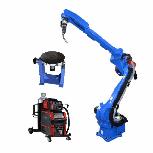
| Positioner | Rotates and tilts the workpiece for flat-position welding | Turntable or headstock-tailstock; AC servo drive; payload capacity (e.g., 1,445 lbs per side) |
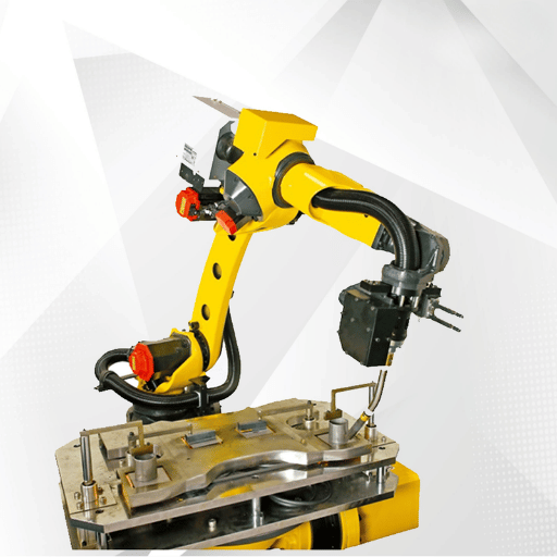
| Fixtures | Hold workpiece geometry within tolerance during welding | Tolerance ±0.022″ for 0.045″ wire per Lincoln Electric guidelines |
| Sensors | Track seam position and compensate for part variation | Laser seam tracking, through-arc sensing, or touch sensing based on joint type |
| Nozzle Cleaning Station | Removes spatter buildup from the torch nozzle between cycles | Automatic reamer with anti-spatter spray; mount within robot reach but away from operator zone |
| Safety Equipment | Protects operators from arc, fumes, and robot motion | Light curtains, physical fencing, interlocks, e-stops per ANSI/RIA R15.06 |
While the industrial robot is the centerpiece, but the positioner often determines if the cell will accomplish cycle time. That servo-driven positioner allows the robot weld to follow a programmed path in flat position at every joint—fastest, best quality orientation—by turning the workpiece instead of forcing the welding arms through dangerous overhead and vertical positions.
Fixtures deserve more design consideration than most shops give them. Fixturing for robotic welding demands tighter tolerances than manual welding. As the robot weld is programmed to follow a path, it cannot adapt on the fly as a skilled welder can. Lincoln Electric’s published specifications require fixture accuracy to within 0.022″ when running 0.045″ wire—roughly half the wire diameter.
Always size your positioner for the heaviest part plus fixture weight — undersizing is the most common and costliest mistake in weld cell planning.
If you are choosing your first robotic welding cell, single robot welding workstation with an integrated positioner and safety enclosure handles the majority of standard applications without the complication of a multi-robot layout.
How Robot Reach and Part Size Shape Your Layout

Six-axis industrial robots produced for welding can handle reach envelopes from 650mm for smaller tabletop units to over 3,000mm for large structural assemblies (Standard Bots guide). The size of the part being welded determines which robot you select and those dimensions in turn determine every other measurement in the cell layout.
Selecting robots follows one rule: size it for the largest part. Installing a small robot on a large workpiece is foolish: the robot can reach only some of the weld joints without repositioning the base—the reposition adds cycle time, floor anchors, and programming complexity. Installing a large robot on small parts is downright foolish: the higher inertia can actually hurt weld quality on thin-gauge material as it overshoots at high speeds.
Design your cell for the heaviest part. Bernard and Tregaskiss recommend sizing the entire cell—the positioner payload, the fixture clamp load, the robot payload—for the largest and heaviest workpiece in the mix. It is far easier to weld a small part in an oversized fixture than it is to squeeze the heavy part into the smaller cell. Designing a weld cell around your largest workpiece prevents costly retrofits when production shifts to heavier assemblies.
In some combinations, size and weight capacity is just as important as reach. A robot arm with only 2,000 mm reach but 6 kg payload won’t be able to carry a heavy MIG torch and its wire feeder. The torch weight, the cable dress, and whatever is mounted to the front all count against the robot’s payload designation. Go over by a hundred grams or three and you have servo faults, path deviation, and early joint failures that impact weld consistency across the entire production run.
Welding at the edge of the reach envelope causes inconsistent torch angles, poor weld quality, and accelerated wear on the cables. Always keep critical weld joints within 85% of the robot’s maximum reach.
When planning your cell out layout, draw an 85% reach circle on the floor plan. Every weld joint in every part in your mix should remain within that circle. If you weld on the edge and one of those joints lands outside it, choose a larger robot or add a positioner to bring the workpiece closer.
Weld Sequence and Cycle Time Reduction Through Layout
Layout and weld sequencing are inseparable. How the robot welds each join relates to heat input balance, distortion management, and the total cycle time – and the physical cell layout either facilitating or fighting the weld sequence.
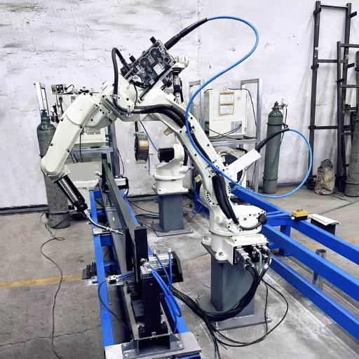
Hard data supports this in proven design. A study surfaced on ResearchGate found 12.7% cycle time savings by simply reordering the weld sequence on a automotive robotic welding cell-two robot welds shaved 68 seconds off a 532 second cycle, bringing it to 464 seconds. Another case uncovered in the book TOA-SE shaved 45% cycle time by switching from a two-robot cell layout to a multi-station six robot layout-even with higher throughput, the cell finished faster:
Cycle Time Reduction Data
- 12.7% saved cycle time-two robot welds going to a new sequence [no hardware changes], (ResearchGate automotive case study)
- -68 seconds efficiency gained on the same parts, same cell-when a six robot cell was reengineered to a multi-station line to improve layout. (TOA-SE case study)
- 45% saved cycle time-upgrading to six-robot cell layout to improve station placement. (TOA-SE case study)
Servo-driven positioners regulate the weld sequence by index-rotating the workpiece while the robot conducts most of the welding tasks. Heat input is more efficient, distortion is minimized, and every joint is layed flat where deposition can progress at a rapid clip with fewer defect rates. The welding process runs faster when gravity assists rather than fights the deposition.
💡 Pro Tip
Position load and unload zones so the operator works while the robot welds. In a dual-station cell, the operator loads a raw part on station A while the robot welds station B. When the robot finishes, the positioner indexes and the robot starts station A immediately — zero robot idle time. This parallel workflow can double effective throughput compared to a single-station cell where the robot sits idle during every load cycle.
One robotic welding workstation incorporating a dual station positioner empowers smaller shops with this parallel workflow efficiency without requiring a conveyor-fed design, separated by a safety screen:
The key: Proper weld quality coupled with speedy cycle times is not a tradeoff. A layout engineered to promote good weld sequence yields both, and the productivity profits with each shift the line can run:
Simulation and Offline Programming Before You Build
Offline programming software lets engineers program the robot on a virtual model of the cell before any physical equipment is installed. According to Visual Components, OLP can be up to 10x faster than teach pendant programming — one documented case cut programming time from 13 hours down to under 3 hours using offline software programs.
Speed, however, is not the main driver in simulation. Collision calculation is. A simulation is capable of detecting interference between the torch and fixture clamps and even the positioner before physical collisions occur. Simulation software can confirm that the robot can achieve all weld joints in the programmed sequence before ever grabbing a real part. The software can further validate that the positioner rotations do not drive parts too aggressively into the robot base, or place too many cable bend limits in jeopardy:
Reachability checks during early design avoid the costliest errors in form layout. When simulation shows the robot cannot reach a weld joint at a given positioner angle, you retire to your computer system to reprogram the cell layout—perhaps relocating the robot base 200mm, altering the positioner height, or rotating the fixture—none of these costs simulation anything and all of them cost thousands in hardware. Take the time to simulate the weld cell layout in offline programming before committing to hardware purchases.
Fixture interference testing is performed in parallel with reachability checking. simulation will import the fixture CAD model and verify that clamp points do not block weld access to any weld joint. If they do, the fixture design gets revised prior to fabrication. This single check eliminates what we see as the most common source of delays in new cell installations stem from fixtures that seem fine in 2D drawings but cause all manner of problems in 3D.
Take the time to simulate the weld cell layout before cutting steel. A $5,000 simulation investment can prevent a $50,000 rework.
Once the cell design is programmed and validated in simulation, the physical build of the cell is mere assembly. The robot control computers ship with functional programs, the fixtures arrive calibrated and ready to install, and commissioning time shrinks from weeks to days.
Pre-Engineered vs. Custom Robotic Welding Cells
Two options face any customer building a robotic welding cell—should you buy a standard package or should you design a custom system? Both options address legitimate customer needs—and both can lead to waste if chosen wrongly.
| Factor | Pre-Engineered | Custom |
|---|---|---|
| Cost | $50,000–$150,000 | $150,000–$250,000+ |
| Lead Time | 4–8 weeks | 12–20 weeks |
| Flexibility | Fixed configurations | Fully tailored to workpiece and workflow |
| Best For | Standard parts, high volume | Complex parts, unique workflows |
| Scalability | Limited | Modular expansion possible |
Cobot welding cells have become the industry’s solution to this dilemma. For entry level installations, $25,000-$50,000 offers a cobot welding cell as an alternative to the safety fencing and floor space constraints of a industrial robot cell. Smaller and slower than industrial robots, cobots allow for robotic automation interchangeability in the work cell with minimal reprogramming once your initial process is set.
Standard positioner size ranges that match your average workpiece dimensions, combined with fewer than five part families per job, make a pre-engineered cell the better ROI choice. The industrial automation system shows up on your loading dock tested and calibrated, ready to make parts within days. Larger, more variable workpieces, combined with specific welding needs and different material handling requirements, makes investment in a custom robotic cell worth your while.
Cost comparisons support these choices—reliable data from industry partners report 1-3 year ROI on most robotic welding systems, with up to 50% materials cost savings in high-volume welding applications. Utilization, more than capital costs, determine overall payback. A $150,000 custom cell used on two shifts pays off faster than a $75,000 pre-engineered cell on a single shift at 60% utilization.
Future expansion is well served by a weld cell layout supports growth when the planning investment leaves room on at least one side of the cell for a second robot or another positioner station. Smart layout of conduit—gas, power, data—with spare capacity today allows upgrade for high-volume welding in the future without a full plant demolition and rebuild.
If your shop is about to commission its first robotic welding project, explore pre-configured welding cells built for production – these include the most common robotic applications for steel structure, plate work and general fabrication, with proven layouts ready to ship to weld. Designing a cell with pre-validated robotics and consumable packages saves months of initial design work.
Safety Zones and Compliance in Weld Cell Design

ANSI/RIA R15.06-2012 is the standard to meet for industrial robot safety in the United States. This covers both robot systems manufacture and deployment and it is the same standard that OSHA turns to when inspecting robotic installs. OSHA does not have a tool-box regulation specific to robotic, but OSHA inspectors and employers rely on ANSI/RIA R15.06 and the general duty clause to determine whether a robotic weld cell layout is safe (ANSI Webstore).
You require a documented risk assessment before you order a single piece of safety equipment for any robotic welding cell. This must identify hazards (arc flash, exhaust fumes, pinch points, floating spatter, robot motion) and assign controls to these hazards. Without a risk assessment, your drive to achieve project deliverables risks design omissions that will undermine the safety of the completed installation. ANSI/RIA R15.06 Part 2 mandates this for every new or changed robot installation, regardless of the type of robotic application or production volume.
These best practices are the safety checks you will review with us before you sign off on a cell layout:
- ✔
Perform risk assessment per ANSI/RIA R15.06 Part 2, documented and signed by a qualified integrator - ✔
Physical safeguards – perimeter fencing, light curtains at load/unload openings, door interlocks with power lockout - ✔
Emergency stop placement within arm’s reach from all operator stations and all maintenance access points - ✔
Welding fume extraction meeting AWS Z49.1 requirements – local exhaust at the arc, not just general shop ventilation - ✔
PPE provisions – auto-darkening welding helmets for nearby workers, flash curtains to protect adjacent workstations - ✔
Anti-spatter protection for sensors, cables, and any exposed robot joints – spatter buildup causes sensor drift and accelerated wear on the cables - ✔
Regular inspection schedule for consumable contact tips, nozzle cleaning station reamers, and gas diffusers - ✔
Lockout/tagout procedures posted at each access gate for maintenance entry into the robot work envelope
MIG and spot welding cells generate the highest spatter volumes of any type of welding process, and that spatter lands on everything inside the enclosure. Welding fixtures, sensor lenses, cable bundles, and the positioner surface all need protection. Anti-spatter compound on fixture surfaces and regular nozzle cleaning cycles prevent the gradual buildup that degrades weld quality over weeks of production.
Good safety practices are not a cost center – they are a productivity premium. Use of a robotic weld cell that minimizes operator doubts and restrictiveness spends more hours per shift than a layout that makes workers nervous about the load zone. Avoiding incidents and having well-organized parts flow and weld sequencing minimizes downtime and extends lifespan of the entire system.
Frequently Asked Questions
Q: How does weld cell layout reduce production time?
View Answer
Well-planned weld cell layouts minimize robot idle time by positioning load and unload stations where operators can work parallel to the welding cycle, the right part order and weld sequencing reduce unproductive movement. Studies have shown over 12% reductions in cycle times in well-planned layouts.
Q: Pre-engineered or custom robotic welding cell — which is right for my shop?
View Answer
Pre-engineered cells ($50K-$150K) can be effective for shops producing standard parts at medium to high volume, with 4-8 week lead times. Custom cells ($150K-$250K+) are more appropriate for shops with large heavy parts, exceptional material flow requirements, or that are planning to grow. Consider your part families, throughput goals, and space availability before making any decision.
Q: Can a robotic weld cell be expanded after installation?
View Answer
Yes, so long as you design for growth. Modular cells with open floor space on one or both sides, universal power and data, and reserve weight capacity (positioners) will support additional robots or stations. Investing in a location flexible layout from the start is 10x cheaper than adding it years down the line.
Q: What safety standards apply to robotic welding cells?
View Answer
The main industrial robot standard in the US is ANSI/RIA R15.06-2012, covering both robot design and system integration. OSHA doesn’t have a robotics-specific standard, but applies the general duty clause and references ANSI/RIA R15.06. AWS Z49.1 addresses welding safety, ventilation, and fume extraction requirements.
Q: How much does a robotic welding cell cost?
View Answer
Entry-level cobot configurations start in $25,000-$50,000. Pre-engineered cells, with a single robot, positioner, and safety enclosure, are $50,000 to $150,000. Fully custom cells, with multiple robots, intelligent sensors, and material handling integration, are $250,000 and beyond. Most machines cost 1-3 years to become profitable through labor savings and throughput increases.
Q: Does the robot need to reach all weld joints in one setup?
View Answer
Not necessarily. A positioner automatically rotates the workpiece to present different weld joints in different positions, and multi-station cells can treat the robot’s weld one part while the operator loads the next. But your layout can only reach all of the joints in the required reach envelope if you don’t reposition the base, which increases cycle time and complexity.
Request a Custom Cell Layout Consultation →
About This Layout Guide
This guide is derived from Zhouxiang’s 30 years in the design and installation of workshops in the steel structure, shipbuilding, and heavy equipment fields. While particular layout advice will vary depending on your workpiece geometry and volume, we have seen similar patterns in over 1,000 completed welding automation projects. We recommend using your own risk assessment and a qualified integrator for all safety and compliance-related decisions.
References & Sources
- OSHA Robotics Standards — U.S. Department of Labor
- ANSI/RIA R15.06-2012 — American National Standards Institute
- IFR World Robotics 2025 Report — International Federation of Robotics
- Fixturing for Robotic Welding — Lincoln Electric
- How OLP Improves Robotic Welding Efficiency — Visual Components
- Cycle Time Optimization in Robotics Welding Cell — ResearchGate
- Work Envelope for Industrial Robots — Standard Bots