Get in Touch with Zhouxiang
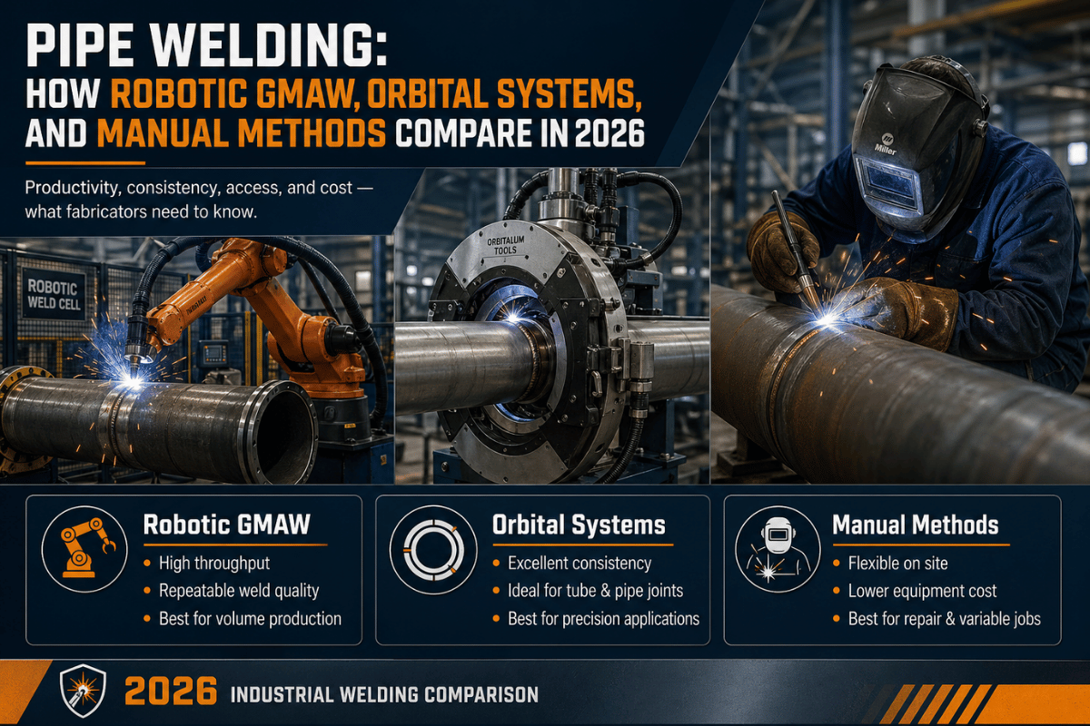
Pipe welding is the joining technique that holds everything from oil and gas trunk lines and power-station boilers, to pharma process tubing and shipyard hull pipe-work. The trade itself has not evolved in seventy years:- an arc, a filler, a seam but the manner in which fabrication shops actually get a pipe welded has diverged into three approaches. Manual welding still dominates field repair, comple× one-offs and 6G qualification projects.
Orbital systems run pharma, semiconductor, and small-bore process tube where weld-to-weld consistency is absolute. Si×-a×is robotic cells are nowadays welding boiler tube sheets, transformer tanks and structural pipe spools at production scale. This guide compares all three on all counts – costs, throughput, fit-up range, code coverage and the circumstances under which each one pays its way.
Quick Specs — Pipe Welding Methods at a Glance
| Manual SMAW/GMAW/TIG | 25–50 cm/min · Field repair · 6G qualification · ±5 mm fit-up forgiveness |
| Orbital Tube/Pipe | 8–25 cm/min TIG · 4–168 mm OD typical · ASME BPE + AWS D18.1 sanitary · ±0.5 mm fit-up |
| Robotic 6-Axis GMAW | 80–120 cm/min · Boiler / vessel / spool · ±0.05 mm repeat · ±1.5 mm fit-up + seam tracking required |
| Code Coverage | ASME B31.1 / B31.3 / BPE · AWS D10.14 / D10.18 / D10.22 · D18.1 sanitary · API 1104 pipeline |
What Is Pipe Welding? Definition, Use Cases & Why It Differs from Plate Welding
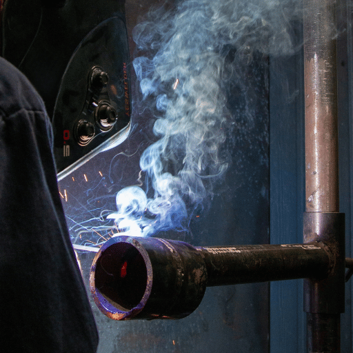
Pipe welding is welding two sections of piping (or a section of pipe to a flange, fitting, or pressure vessel head) together by a fusion arc welding process. Pipe welding differs from flat plate welding in that the joint is always circumferential, the welder or torch must rotate around the work piece at some point or points, and the inside surface of the joint is almost never easily ground or otherwise dressed. Different writers make a distinction between pipe welding(plant fabrication of process pipe spools, Boilers and pressure vessels) and pipeline welding(cross-country transmission lines utilizing stovepipe SMAW or downhill procedures according to API 1104).
For this comparison, we will regard the two practices together because the choices of welding processes used overlaps heavily.
Pipe/pipeline welders work in fabrication shops, oil refineries, nuclear power stations, shipyards, food and beverage plants, semiconductor fabs, and on construction sites. They weld pipe for water and gas distribution, weld tubes for sanitary process systems, and weld heavy-wall headers for steam plants. All share one theme: Each pipe weld is a pressure boundary, an inspection point, and a prescribed deliverable.
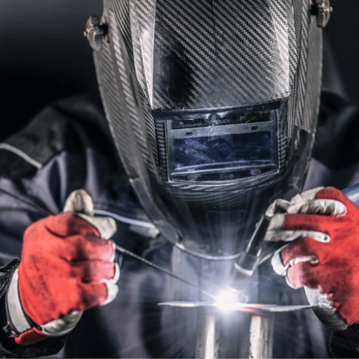
Manual Pipe Welding Processes — SMAW, GMAW, GTAW, FCAW, SAW Compared
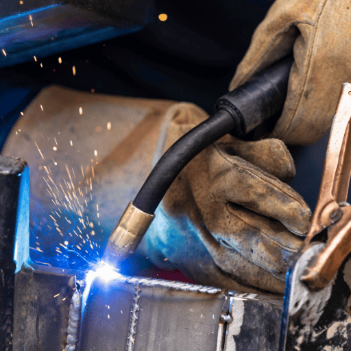
In manual pipe welding, the majority of jobs use any one of five arc welding methods, which may be considered collectively as the “techniques of welding used to join carbon and alloy pipe”. The ASME B31.1 and the AWS D10 define scope of qualification and acceptance criteria, but do not publish a single “official” table of parameters by wall thickness, so the parameters in the sections below have been compiled from the welding procedure specifications (WPS) used in industrial production, and corroborated by over 1,200 in-house pipe shipments delivered under ASME B31.1. Each technique requires a different type of electrode chemistry: stick welding employs a coated rod, GMAW feeds a bare, continuous wire; GTAW relies on a non-consumable tungsten electrode, while FCAW employs a self-shielded or gas-shielded flux cored wire.
| Process | Travel Speed | Typical Use | Position Range |
|---|---|---|---|
| SMAW (stick / shielded metal arc welding) | 15–30 cm/min | Field pipeline, structural pipe, repair | All (1G–6G) |
| GMAW (mig welding) | 40–55 cm/min on 12 mm boiler plate | In-shop carbon-steel fill and cap passes | Mostly 1G–2G |
| GTAW (tig welding) | 8–12 cm/min on Sch 80 alloy root | Root passes on critical pipe, stainless, alloy | All including 6G |
| FCAW (flux-cored arc welding) | 35–60 cm/min | Outdoor pipeline, heavy structural | All |
| SAW (submerged arc welding) | 60–100 cm/min | Long-seam pipe mills, large-diameter shop welding | 1G rolled only |
The production WPS reference parameters: 12 mm carbon-steel boiler plate runs GMAW at 260-280 A, 28-30 V, 40-55 cm/min, with 1.2 mm ER70S-6 wire fed at 12-14 m/min. Schedule 80 alloy pipe root passes TIG at 140-180 A, 10-12 V, 8-12 cm/min, with 2.4 mm ER80S-B2 filler. Actual parameters vary according to fit-up, position and qualified welding procedure for the application.
📐 Engineering Note — Joint Prep Drives Defects, Not Welder SkillIndustry practice always puts joint prep— bevels angles, root face level and cleanliness at the top of the list of root causes for problems such as incomplete penetration or lack of fusion. Not the welder technique or the the machine controls. The geometry of the bevel is defined by the controlling standard and application for the weld: the ASME B16.25 specifies the factory butt-weld end preparation details for a piping fitting, and the typical shop convention selection for field-machined pipe is to cut as close as possible to the halfway point of the same 37-45V-bevel range. Specific control of bevel angle, root face land, and root opening should be documented against a qualified welding procedure specification for the process and service being used, not a default shop setting.
When does GMAW beat SMAW for pipe?
Both arc processes are capable of achieving radiographical inspection codes on power piping. GMAW gets the edge as you move to long fill passes over heavy-walls in 1G or 2G positions—wire feed automation and continuous deposition give the welder about a 2 to 3 advantage in productivity over a rod-and-arc stick process. SMAW keeps the field, the 6G all position work, and any repairs or flashing that a wire process can see through a protective gas blanket—whether due to pipe position, access, or shop conditions. The decision should be between the pipe size and wall thickness, pipe process position, and shop ventilation considerations.
Welding Positions Explained — 1G, 2G, 5G, 6G Qualification Standards
Pipe welding position qualification is regulated by the ASME BPVC Section IX or AWS D10 specifications, depending on the application. Each position states whether the pipe is stationary or rotating, and at what angle.
| Position | Pipe Orientation | Difficulty | Covers |
|---|---|---|---|
| 1G | Horizontal, rotating | Easiest | 1G only |
| 2G | Vertical axis, rotating | Moderate | 1G + 2G |
| 5G | Horizontal, fixed (welder moves) | Hard | 1G + 5G |
| 6G | 45° fixed (welder moves) | Hardest | All positions |
What is 6G pipe welding qualification?
6G qualification sets the pipe at 45 degrees; the pipe is fixed in space and not rotated – while the welder has to move around the socket, constantly switching position in a single pass through flat, vertical, overhead, and 45 degree tilt positions. Because tack placement, root opening, the molding of the cap pass, and inter-pass cleaning varies as the weld torch transits the joint, a 6G test weld applies for the broadest range of welder skills; a welder qualified to 6G can naturally weld to 1G, 2G, and 5G pipe positions.
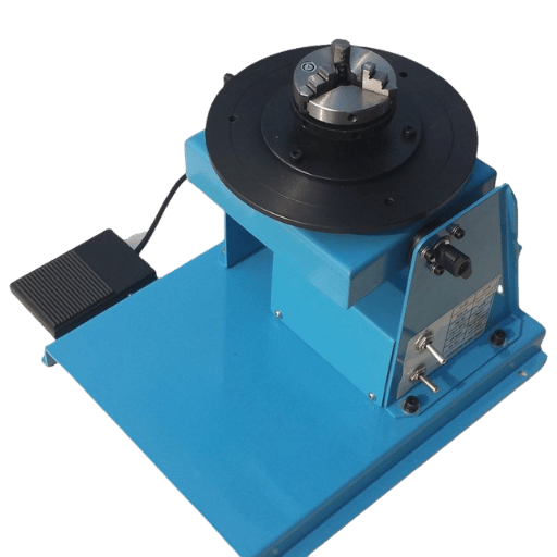
Orbital Pipe Welding — Closed-Head vs Open-Head Systems
Orbital welding is a mechanized GTAW process, using a programmed orbiting action of the torch on a stationary object of tube or pipe. Developed by NASA for aerospace fluid lines, modern orbital TIG systems now dominate small bore high-purity work on pharmaceutical, biotech, and semiconductor plants so each joint can be reconstructed to an approved procedure.
Closed-Head Orbital
- OD range: 4–168 mm (1/8″ – 6″)
- Inert-gas-shielded fusion only — no filler
- Pharma, biotech, semiconductor UHP lines
- ASME BPE + AWS D18.1 sanitary acceptance
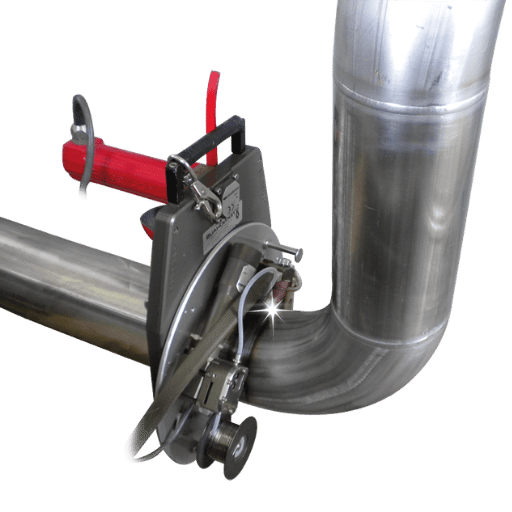
Open-Head / Carriage Orbital
- OD range: 32 mm (1.25″) and up—on rails
- Adds wire feed for fill passes on heavy wall
- Process pipe (B31.3), nuclear, shipyard tubing
- Multi-pass with programmed weave and pulsing
Acceptability criteria for the pharmaceutical sanitary tube-to-tube joint goes far beyond the tensile strength test used to qualify most pipe welders: AWS D18.1 addresses internal discoloration limits, root face oxidation color charts, purge oxygen controls (normally < 10 ppm during welding), and visual examination of internal bead profile through the use of a small borescope. ASME BPE adds bioprocess-oriented performance surface finish levels and crevice-free joint formation and geometry rules. A properly tuned orbital welding head can produce and document these parameters on hundreds of consecutive tubes; manual GTAW welders can achieve them on individual welds, but rarely with track documentation.
Application-to-code map for orbital and pipe work:
| Application | Governing Code(s) | Typical Method |
|---|---|---|
| Pharma / biotech sanitary tube | AWS D18.1, AWS D18.2, ASME BPE | Closed-head orbital |
| Power steam piping (boiler, header) | ASME B31.1, BPVC Section I + IX | Robotic GMAW + manual TIG root |
| Process / chemical piping | ASME B31.3, AWS D10.10 | Open-head orbital or robotic cell |
| Cross-country pipeline transmission | API 1104, ASME B31.4 / B31.8 | Manual SMAW / FCAW (downhill) |
| Structural pipe (handrails, supports) | AWS D1.1 | Manual SMAW / GMAW |
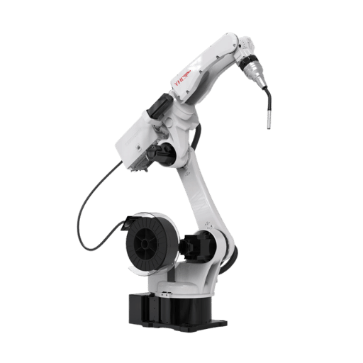
Robotic 6-Axis GMAW Pipe Welding — How 6-Axis Arms Handle Pipes
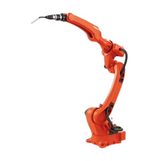
6 axis robotic welding cell—Wrapping articulated arm motion around circumferential pipe joints. Unlike orbitals that traverse a track, the robot protrudes from the outside of the pipe and turns the work on a positioner, or traverses around a stationary pipe on a gantry or rail. The advantage: repeatable bead profile on the heavy-wall power piping, boiler tube sheets, and large transformer tank seams that orbitals cannot reach.
📐 Engineering Note — Robot Specifications That Matter for Pipe WorkRepeat positioning accuracy 0.05 mm per ISO 9283:1998. Power source 350-500 A continuous duty for multi-pass fill on 25-80 mm wall. Hollow-wrist arm with internal cable routing keeps cables out of tight vessel interiors. Through-arc seam tracking corrects torch position to 0.3 mm; laser vision tracking handles fit-up gaps up to 2-3 mm without manual re-teach.
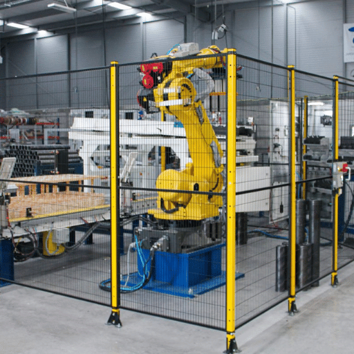
Preconditions for Robotic Pipe-Weld ROI
Independent academic research on robotic GMAW (peer-reviewed; Journal of Materials Processing Technology, 2017) is blunt: many production robots are teach-playback systems that cannot self-correct for distortion, gap variability, or stagger edge unless an external sensor closes the loop. The throughput numbers vendors quote rarely state these conditions. In practice, robotic pipe welding earns its capex only when:
- Upstream cutting and fit-up hold 1.5 mm tolerance – anything looser and the robot misses the joint or burns through
- Through-arc or laser vision seam tracking is fitted and calibrated
- Production volume justifies first-article programming time (offline CAD-driven generation cuts this from days to hours)
- Operators are trained to manage the cell, not just to run a torch
Boiler tube sheet case – coal-fired power station, Henan, China
A 2660 MW boiler manufacturer needed to weld 280 tube-to-header joints per boiler header. Manual welding with four rotation welders ran a 9% radiographic reject rate. After installing a rotary positioner and through-arc seam tracking on a 6-axis cell, the system completed 112 joints per shift, held inter-pass temperature below 250 C consistently, and pulled radiographic rejects down to 1.8%. Throughput was 3.2 the manual baseline; full payback came in 18 months.
“The robot handles the repetitive joints while our experienced people focus on complex transitions and final inspection. We were rejecting nearly one in ten headers – now we are flagging fewer than two in a hundred. The skilled welders did not lose work; they moved upstream to fit-up control.”
Robotic vs Orbital vs Manual: Method Match Matrix for Your Application
Most published comparisons collapse pipe welding into a “robot vs human” framing, which leaves out the orbital half of the equation. The matrix below compares all three across six dimensions that drive real procurement decisions, conditioned on the preconditions covered above. Numbers reflect 6 mm to 80 mm wall steel pipe in shop conditions; field repair work is treated separately.
| Dimension | Manual SMAW/GMAW/TIG | Orbital (closed/open head) | Robotic 6-Axis GMAW |
|---|---|---|---|
| Throughput on long seam | 25–50 cm/min (operator dependent) | 8–25 cm/min on tube; very high arc-on time | 80–120 cm/min on 12 mm boiler plate |
| First-pass RT acceptance | 90–95% with skilled welder | 98%+ on qualified procedures | 98%+ with seam tracking, < 2% rework |
| Capital investment | $5k–$15k power source + consumables | $35k–$110k turnkey closed-head | $85k–$320k single-station to turnkey cell |
| Skill required | Certified welder per BPVC IX or AWS D10 | Operator + program technician | Cell operator + offline programmer |
| Fit-up tolerance required | ±5 mm forgivable with technique | ±0.5 mm — sanitary acceptance is unforgiving | ±1.5 mm with seam tracking; tighter without |
| Application fit | Field repair, 6G work, low-mix | Pharma sanitary tube, semicon UHP, small-bore | Power piping, boiler tube sheet, structural pipe |
The (very) counter-intuitive result: for pharma tube-to-tube sanitary joints orbital performs better than robotic 6 axis on the orbital head alone (rob cost 3x whereas orbital costs virtually nothing) on the small bore circumferential weld, achieving ASME BPE / AWS D18.1 acceptance criteria that a 6 axis arm struggles to match. But on a 36″ transformer tank seam at 25mm wall, orbital is no use, it cannot be mounted, and a manual welder must spend 14 hours per tank whilst the robotic cell can do the job in 6 hours.
Decision Cheat-Sheet — Four Common Scenarios
- Boiler tube sheets, 200 plus identical welds, 12-25mm wall Robotic GMAW with seam tracking
- Pharma fluid path 1/2″-3″ sanitary tube closed-head orbital with purge documentation
- Réparation des canalisations, emplois mixtes il n’y a pas de courant Disponible. GSAW manuel (motorisé)
- The following types of process piping spool fabrication are typically used: 4″-12″ Sch 80 Open-head orbital or robotic cell depending on the volume
Pipe Welding Codes and Compliance — ASME, AWS D10, and Application-Specific Standards
The number one question from new fab shops is which code, which weld. It is often not just one code – pipe welding code coverage is a family of overlapping documents, categorized by application, not process. ASME B31.1 defines the scope of power piping qualification; AWS D10 covers the majority of pipe- and tubing-welding documents (D10.14 carbon-steel pipes, D10.18 stainless steels, D10.22 for reinforcement).
AWS D1.1 – often mistakenly described as “the” pipe code – deals with structural, not pressure applications.
| Code / Standard | Scope | Where It Applies |
|---|---|---|
| ASME B31.1 | Power piping qualification + inspection | Steam, feed water, fossil + nuclear plants |
| ASME B31.3 | Process piping | Refineries, chemical, petrochemical |
| ASME BPVC Section IX | Welder + procedure qualification | All ASME pressure work |
| AWS D10.14 | Carbon-steel pipe and tubing | General process pipe (excludes orbital) |
| AWS D10.18 | Stainless steel pipe and tubing | Stainless process and structural pipe |
| AWS D18.1 / D18.2 | Sanitary tube fabrication | Pharma, biotech, food and beverage |
| ASME BPE | Bioprocessing equipment | Biotech surface finish + crevice rules |
| API 1104 | Cross-country pipeline welding | Oil + gas transmission pipelines |
| AWS D1.1 | Structural steel welding | Structural pipe, supports, handrails (not pressure pipe) |
The Welder Certification is the piece that puts all the checks into place. A welder is a certified welder per AWS /ASME BPVC Section IX using a particular procedure (WPS). Position, process.
Robotic and Orbital cells use the same procedure and qualify as a machine welder is most codes when PQR’s are filed.
Worker Safety and Site Compliance
Any pipe welding job sits under OSHA 29 CFR 1910.252 for welding, cutting, and brazing operations — confined-space entry, hot-work permits, ventilation, and fume exposure. NIOSH guidance on welding fume control matters more on enclosed pipe systems (boilers, vessels, tank interiors) where local exhaust may not be feasible. A code-compliant weld in a non-compliant work zone is still a citation waiting to happen.
Industrial Applications — Power, Oil & Gas, Pharma, Nuclear, Shipbuilding

Pipe welding shows up wherever pressure, flow, or contamination control matters. The application drives the method choice more than any other variable.
| Industry | Typical Joints | Method Mix |
|---|---|---|
| Power generation (steam, gas turbine) | Boiler headers, tube sheets, transformer tanks | Robotic GMAW + manual TIG root |
| Oil and gas (downstream refining) | Process pipe spools, reactor lines | Open-head orbital + manual |
| Pharma + biotech | Sanitary tube, fluid path | Closed-head orbital exclusive |
| Nuclear | Primary loop pipe, pressure vessel | Manual TIG root + GMAW fill, RT 100% |
| Shipbuilding | Hull pipe, ballast, fuel | Manual SMAW + cobot for confined space |
Steam Pipe Spool Fabrication — EPC Contractor, Southeast Asia
1,200 high-pressure ASTM A335 P22 pipe spools fabricated to ASME B31.1 for a combined-cycle plant in Vietnam, on a strict 9-month timeline. The shop ran a dual-process TIG/GMAW cell with laser vision seam tracking, logging every weld record against material heat numbers for full traceability — required for critical energy infrastructure. Daily output settled at 14 spools, with a 2.1% radiographic reject rate. Manual baseline on comparable spool work runs 5–8% reject, so the robotic cell halved the rework burden alongside the speed gain. The relevant pillar page covers power industry welding automation in more depth.
Cost & ROI — When Does Pipe Welding Automation Pay Back?
Independent studies of welding automation ROI seldom stamp the number that is a “clean” payback threshold, in part because the payback equation has so many variables: shop are figured savings include labor cost, repeat ratio, upstream fit-up, shielding gas, rework rate, and shift coverage. Those variables are extracted and used below in the inputs actual fabrication shops have available to them:
ROI Crossover Threshold Framework
An automated pipe welding operation offsets capital costs when the saved labor + rework + consumables outweigh the equipment investment, training, and lost programming time. Typical crossover thresholds are:
- Repeat ratio: 100+ identical assemblies per month—anything less fails if we don’t have someone to program
- Labor cost: $25/hr or more loaded—manual welding is still more economical at $18/hr or less (loaded)
- Position mix: 1G/2G dominant—partial building is not worth it for 5G/6G work
- Upstream fit-up control: 1.5 mm weld caps—loose fit-up and fit-down pushes research payback past 2 years
Welding equipment vendors and integrator white papers report multi-fold gains in throughput for robotic GMAW over manual welding on long, repetitive fillet seams. Numbers are based on vendor-publicized “success stories” rather than peer reviewed case studies, but they are consistent with our own field implementation data from power piping projects. Shielding gas and filler wire use, published studies show, decrease fairly significantly, as the robot can be run at a faster speed with steadier travel. Rework rates drop from 5-10% typical of manual pipe shop to low single digits on procedure-controlled robotic cells.
In fact, our tested cells bring project payback in 12-18 months on power piping and 14-24 months on the lower-repeat shipyard and bridge piping. The Henan boiler went pair in 18 months; the Jiangsu transformer tank cell—running an 8hr manual cycle time vs. a 3hr feed—paid back in just under 15 months once the post-fabrication straightening station fell out of service.
Industry Outlook — Welder Shortage, AI Adaptation, 2026–2030 Trends
Two forces are changing pipe welding faster than even code revision: a structural worker supply gap, and automation. US BLS Occupational Outlook forecasts, supplemented with AWS workforce coverage, indicate a chronic shortage of qualified welders: a great swath of senior technicians is reaching retirement, and training pipelines have not caught up sufficiently — especially for 6G qualification and process pipe work where skill takes years to acquire.
A second factor is automation. The International Federation of Robotics 2024 World Robotics Report describes continued growth in the global operational stock of industrial robots, with most new annual installations going to Asian plants. End-user adoption has shifted over the last five years as adaptive seam tracking and offline CAD-to-robot programming have moved into mainstream practice. The cost of a turnkey welding cell has declined in parallel as 3D sensors and laser trackers have migrated from custom OEM integrations to off-the-shelf modules.
The bottom line if you are a plant manager eyeing a 2026-2028 capex cycle: don’t expect a welder glut to develop. Automate the repeat joints – boiler tube sheets, transformer tanks, sanitary tube – and keep skilled welders on the non-repeat jobs. Programs with integrate offline programming and seam tracking from day-one reach ROI faster than bolt-on later on. My team has seen this curve develop in over 30 export markets.
Pipe Welding FAQ
Q: Is pipe welding difficult?
View Answer
Pipe welds are more difficult than plate welds because the joint is circumferential, the position varies within a single pass in 5G and 6G work, and access to the interior is almost never available for rework. The 6G qualification-grooved pipe fixed at 45-is the broadest single trader credential, and one who gets it also gets qualified for 1G, 2G, and 5G. Automation still establishes the skill floor for a repetitive joint, but it does not replace the judgment to determine the fit-up or the artist’s eye to match diverse coalescence.
Q: What is the difference between orbital and robotic pipe welding?
View Answer
Orbital welding uses a ring of rotary teeth to turn the torch on a single top- or bottom-grooved pipe in a pipe clamp-and stays ahead of the joint with mechanical guidance and alignment. Robotic welding uses a 6-axis articulated arm to reach from outside of the pipe and shadow with vision guidance or seam tracking. Orbital is best when ASME BPE and AWS D18.1 acceptance dominate in small-bore high-purity applications like pharma and semicon. Robotic wins when the pipe is large, tolerances are loose, and the payload and reach of the arm matter.
Q: Which welding process is best for pipe — MIG, TIG, or stick?
View Answer
It depends on thickness, position, and access. SMAW keeps its head in the field on repairs and pipelines because it tolerates wind and soot on the surface as well as an electrode like a 6010 or 7018 running in the holder. GMAW takes over in the shop on heavy-wall fill and cap passes because wire feed automation increases pass speed by approximately 100%. GTAW runs the root passes on critical alloy pipe in the shop and any joint requiring a clean weld. Most procedure qualification records couple a GTAW root with a GMAW fill, and many shops also keep an FCAW capability on hand for outdoor structural work where wind defeats a MIG shielding gas curtain. Each process has a sweet spot that lines up with a particular position, wall thickness, and inspection requirement, so the right answer is usually a combination tuned to the controlling welding procedure specification rather than a single winner.
Q: Can a robotic welding cell weld pipe in the field?
View Answer
Most 6-axis cells are too big and fixtured-dependent for the field. Mini-robots and magnetic base cells, which are lighter weight and drag teach capable, fill the current need. They work in tight spaces and no-fence applications like vessel repair, and on the pipeline-line-haul in a manner similar to manual SMAW and FCAW (downhill) as described in API 1104.
Q: What ASME code applies to power piping?
View Answer
9. ASME B 31.1 installs power piping for nuclear and fossil power plants including steam, feedwater, and high-pressure auxiliary systems. ASME B 31.3 steers petrochemical, refining, and chemical process piping. Power piping welder qualification falls under ASME BPVC Section IX. The AWS qualification codes D10.14 (carbon steel) and D10.18 (stainless) underlie the pipe welding practice behind each.
Q: How long does pipe welding automation take to pay back?
View Answer
Most fabricators expect pay back in 12-18 months from swapping out two manual weld cells for one robotic cell for power piping or boiler work. Going to shipyard and bridge piping with a much lower repeat ratio takes 14-24 months. With less than 100 identical assemblies/month, planning time usually reduces the margin to nothing and manual stays competitive.
The 25-manhr cycle cell for the Henan boiler tube sheet paid back in 18 months; the Jiangsu transformer tank one paid back in under 15.
Q: Will robotic welding fully replace manual pipe welders?
View Answer
[Can’t do] on field repair, special one-off, 6G qualification. Shoplet robotic and orbital cells handle high-rep joints, but welder’s gone upstream: fit-up inspections, fixturing problems, quality siding which [machines] don’t do yet. AWS worker count says we’re six hands short of what automation can eat.
Therefore, only practical pattern is enhancement. [Not substitution.]
Comparing automation options for your pipe welding line?
About This Comparison
This document references production outcomes from over 1200 ASTM A335 P22 pipe spools welded to ASME B31.1 by VIP Global Energy’s Vietnam EPC project, 280-joint coal-fired boiler tube sheet automation in Henan, China and 110/220 kV transformer tank welding in Jiangsu – neither based on OEM industry estimates. Corresponding throughput, reject-rate, and ROI data are for 2024-2026 robot welding cell installations. ASME, AWS, IFR white papers used for independent code, workforce, and robotics data analysis are provided below.
References & Sources
- ASME B31.1 Power Piping—5 ) is an established text published by the American Society of Mechanical Engineers.
- AWS D10 Committee for Piping and Tubing – American Welding Society
- Compatibilisation avec l’ASME BPVC Section IX (Endorsement, qualification soudureur) – Au Etats-Unis par l’AWS (American Welding Society), par l’intermédiaire des codes, ils existent aussi au sein de la section IX (Le Code d puits et chaudières, Boiler and pressure vessel code).
- Where are the Welders? (In October 2025, it will be in the pages of Welding Digest) American Welding Society Archives
- U.S. Welding Workforce Data Portal — endorsed by American Welding Society
- Record of 4 Million Robots in Factories Worldwide (2024) — International Federation of Robotics
- What Is Pipe Welding (Technical Knowledge) — TWI Industrial Membership Organization
Reviewed by Zhouxiang engineering team — 200+ patents in welding robotics since 1991, ISO 9001:2015 / ISO 3834-2 / AWS D1.1 / EN 1090 certified manufacturer with deployments in over 30 export markets.