Get in Touch with Zhouxiang
How to Choose the Right Welding Robot for Your Production LineThe global talent shortage for welders is no longer a prediction — it’s the reality felt every day on fab shop floors. The American Welding Society (AWS) estimates the U.S. will require about 330k new welding guild members from now through 2028, while the median age in today’s welding workforce is 55. With that backdrop, more and more makers are looking at welding robot systems—but choosing the wrong robot welder can bleed six figures of capital without benefits.
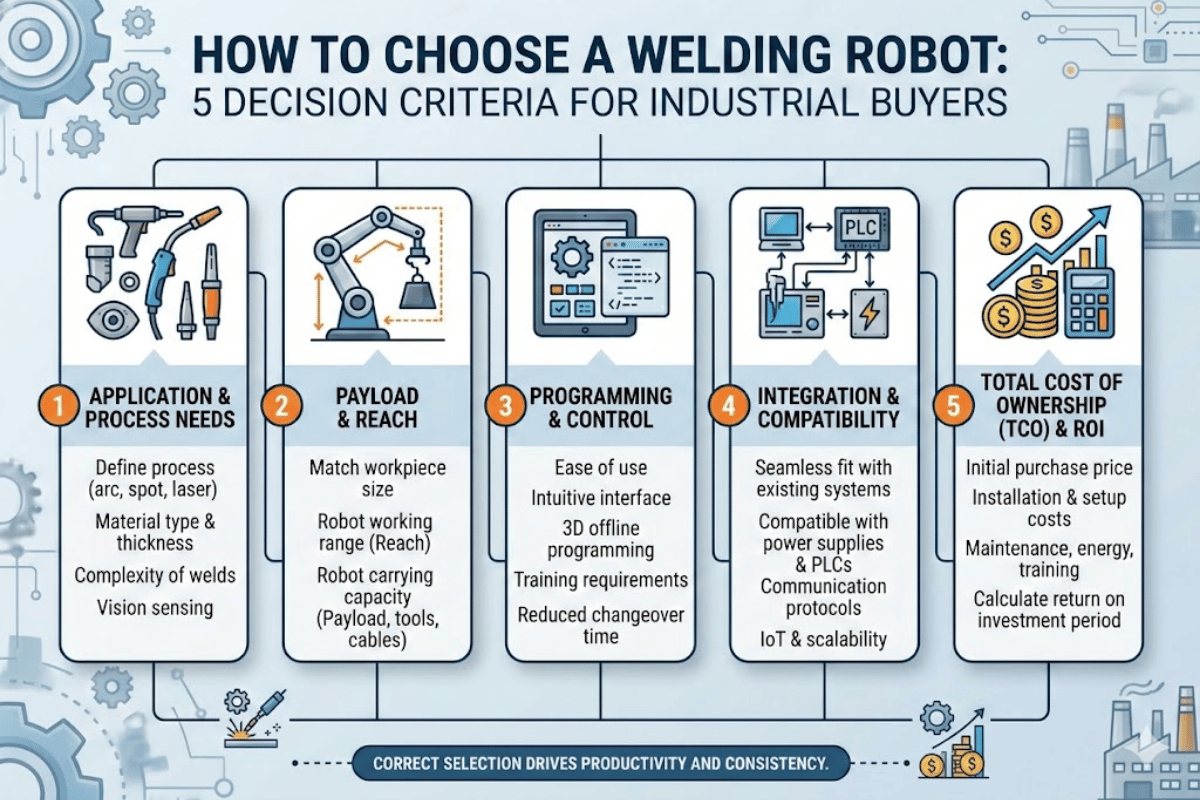
This guide introduces five decision factors industrial buyers use to select the right welding robot. Each includes actual specs data, cost context, and pitfalls for newcomers.
Why the Right Welding Robot Makes or Breaks Your Automation ROI

Robotic welding is the second-largest purposes for industrial robots globally, comprising around 15-21 percent of installations. The IFR World Robotics 2025 Report indicates, from 2024, factories installed roughly 542,000 new robots—a trend that’s doubled in the last 10 years. The main driver? Manufacturers who cannot adequately resource manual welding tasks.
According to Bureau of Labor Statistics data, close to 45,600 welding position vacancies open each year, often to replace retirements. Meanwhile, robotic welding machines generally achieve 60-85 percent arc-on time—compared to 20-35 percent for a welder—all day long. That productivity gap is what manufacturers find so appealing—but only if the robot matches the welding tasks at hand.
542,000
Robots installed globally (2024)
330,000
Welders needed in the U.S. by 2028
60–85%
Robot arc-on time vs. 20–35% manual
⚠️ Common Mistake
Choosing a robot based on price alone. For every dollar spent on the robotic arm, another 70 cents is typically absorbed into the power source, fixturing, safety cage, integration labor, and operator training.
Criterion 1 — Match the Welding Process to Your Application

Your welding process determines every subsequent decision— torch specifics, shielding gas type, wire thickness, welding parameters, and even the payload of the robot. Before reviewing any candidate models, identify which of the different welding processes your parts require.
MIG / MAG (Gas Metal Arc Welding)
MIG welder robots are by far the most widely adaptable to various production welding tasks. They spin filler through a continuously-fed wire stick, shielded in a gas-based by an inert or active gas. Steel variants, aluminum variants, all of these work in MIG. Structural-strength parts with high deposition—like beams, gussets, and stability braces—often default to a MIG welding robot.
TIG (Gas Tungsten Arc Welding)
Where MIG welded for speed, TIG welded for accuracy. Non-melting tungsten outputs a narrow, clean weld bead with little to no spatter. Applications where appearance or metallurgical condition takes precedence—such as aerospace and foodgrade stainless steel components, and small-hose thin-walled pipe—often go for TIG bonding rather than high-volume efficiency.
Laser Welding
Laser welding robots focus a concentrated beam of light energy to fuse metals—keeping the heat-affected zone tiny. Travel speeds can reach several meters a minute—distortion stays minimal. That matters for assemblies built to tight tolerances. Capital expense runs higher, but the payback comes fast with volume and repetitive welding.
Spot Welding
Spot welding still accounts for the majority of automotive body-in-white production. Two copper electrodes squish down onto sheet metal panels and drive current through until a resistance weld “nugget” forms. Robot payloads may be over a hundred kilograms for the spot welding guns; the choice of robotic arm will primarily be governed by the weight of the gun and the reach to each weld location.
| Process | Best For | Speed | Precision | Entry Cost |
|---|---|---|---|---|
| MIG / MAG | Carbon steel, stainless, aluminum; structural fabrication | High | Moderate | $$ |
| TIG | Thin materials, aerospace, food-grade stainless | Low–Moderate | Very High | $$$ |
| Laser | High-volume, tight-tolerance assemblies | Very High | High | $$$$ |
| Spot | Sheet metal, automotive BIW, panel joining | High | Moderate | $$ |
💡 Pro Tip
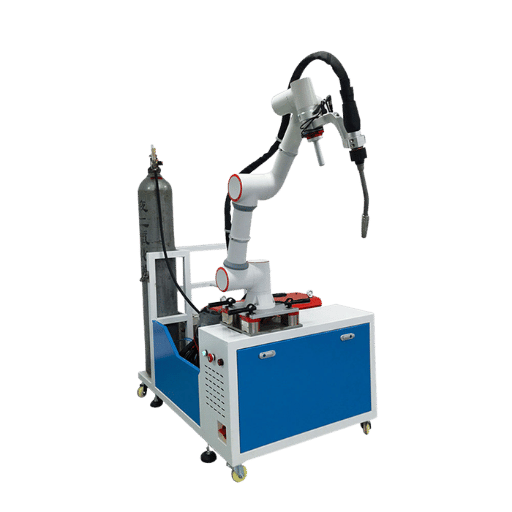
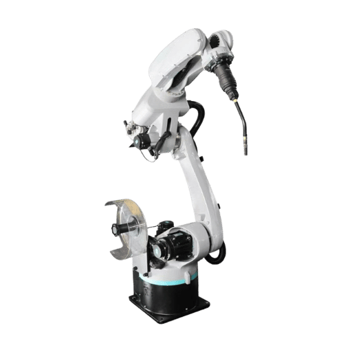
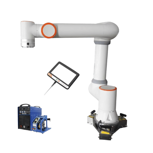
Some of today’s newer robot models can perform multiple weld types on the same arm. Zhouxiang’s all-in-one ground-rail welding robot, for instance, is capable of gas-shielded MIG, argon-arc TIG, and laser welding processes loaded on a single six-axis platform. If your production schedule requires different materials and joint types, one multi-process robot can replace multiple dedicated cells.
Criterion 2 — Evaluate Payload, Reach, and Axis Configuration
Every welding robot must physically carry the torch assembly, along with wire feeder, cables, and the optional sensor package, to each weld joint location. Sizing down the payload or reach capability can result in missed weld positions during complex welding operations, additional fixturing, or a re-tooling upgrade post-delivery — reducing the benefits of robotic welding before the system even starts production.
Payload
Arc welding torches with integrated wire feeders will usually have masses in the 6-12 kg range. Including a built-in camera or seam tracking sensor means a wrist loading approaching the 15 kg mark. Always spec the payload with a generous safety margin of at least 20 percent above the actual requirement. As an example, the Zhouxiang ZXR12-2010 is a 12 kg payload, while the ZXR10W-1440-D can manage a 10 kg load – both more than enough for TIG and MIG welding equipment.
Reach (Arm Radius)
Reach determines the size of the work envelope. A 1440 mm reach is fine for small-to-medium weldments less than a meter long. Welding large steel structures such as plate columns, platform-level support beams, or ship bridge sections will need a reach in excess of 2000 mm. When the part or fixture cannot be reached with even a long-reach robot, ground-rail systems extend the workspace. Zhouxiang’s standard 6 m rails are easily extended to custom lengths for long seam welds.
Axis Count and Mounting
Six axis robots are the industry standard in arc welding applications. Its sixth axis lets the torch approach from nearly any angle. Seven-axis systems evolve to an additional axis of motion for working in tight workspaces or when traveling partially behind fixtures. Mounting versatility – floor, ceiling, wall brackets, or inverted – determines how much floor space the welding cell consumes.
| Spec | ZXR12-2010 | ZXR10W-1440-D |
|---|---|---|
| Axes | 6 | 6 |
| Payload | 12 kg | 10 kg |
| Reach | 2,010 mm | 1,440 mm |
| Repeat Positioning | ±0.05 mm | ±0.05 mm |
| Weight | 313 kg | 210 kg |
| IP Protection | J1–J2: IP56 / J3–J6: IP67 | J1–J2: IP56 / J3–J6: IP67 |
| Mounting | Floor / Bracket / Inverted | Floor / Bracket / Inverted |
💡 Pro Tip
Find IP67 rated wrist joints. Welding spray, grinding dust and splatter, and humid air from cooling lines will significantly reduce welding robot life if they are not protected correctly. IP67-rated seals on axes J3 through J6 will allow water tube, grind gun and weld spatter – as well as temporary immersion – to not compromise the joints’ internal hardware.
Criterion 3 — Assess Production Volume and Part Complexity
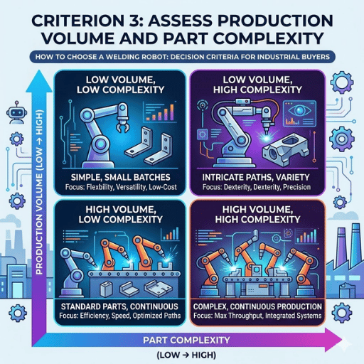
Cell configuration depends far more on your typical production mix than on any single technical factor. A factory producing six hundred alike brackets per shift will plan quite differently from one that welds twenty different structural frames a week.
High Volume, Simple Geometry
If the weld process requires no variation but to repeat on each cycle, then a simple single station cell will be most economical. Program instructions stay the same for each cycle, while a stationary table – rotary positioner or fixed table option – may hold the piece being welded.
High Volume, Complex Geometry
Work with many welds at different angles, or hard-to-reach seams? Multi-station welding cells with servo-driven positioners can help. While the robot is welding at Station A, an operator loads a new part at Station B. Positioners tilt and rotate the workpiece so every joint is optimized for its best weld angle instead of requiring unwanted torch-angle compromises.
Low Volume, High Mix
Parts with many different part numbers? Off-line programming software is the solution. Operators simply load 3D CAD drawings–Tekla, Solid Works, or UG–and they generate robot program paths on a normal desktop computer without taking the cell down. Teaching-free programming avoids hours of jog-teach that make small-batch automation uneconomical on older systems. These automated welding systems let skilled welders focus on welding tasks with precision that robots cannot yet replicate.
Simultaneous seam-tracking can dramatically improve welding consistency and flexibility. A laser line-tracker like the CP350V sensor on Zhouxiang rail systems can measure the actual joint location during welding and correct the torch path to offset any part-to-part variation. This is especially important in structural steel and heavy-plate welding where distorting tack welds can shift a joint by 3-4 millimeters.
Choosing the Right Cell Configuration
- 500+ identical parts/shift → Single-station cell with fixed fixture
- 200–500 parts/shift with multi-angle joints → Dual-station with servo positioner
- Under 50 parts/shift with many part numbers → Modular cell with offline programming + seam tracking
- Long-seam structural work (beams, columns) → Rail system with extended travel
Criterion 4 — Industrial Robot vs. Collaborative Robot (Cobot)
Not every welding automation project requires a robot welding system behind a safety fence. Collaborative robots–cobots–have established an important role in welding now, thanks to their lower first costs and ready adaptation to low-volume applications. It comes down to speed, throughput, and floor space.
When an Industrial Robot Wins
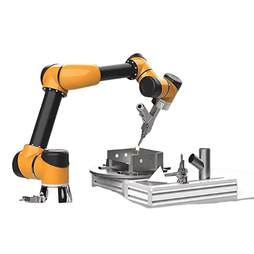
Industrial robots are designed for maximum throughput. They operate at higher speed (tool speeds of 2 meters per second are commonplace), can support much heavier payloads, and sustain a duty cycle that keeps the arc active 85 percent of a shift or more. If your workflow operates two or three shifts, welds heavy plate, or must accommodate multi-station cell ergonomics with safety-rated hardware, an industrial robot is the right choice for using robotic welding at scale.
When a Cobot Wins
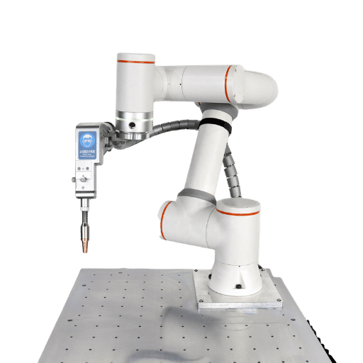
Cobots do not have the high-rate performance of industrial robots, but they are much easier to operate. A cobot does not need a safety enclosure–it can be equipped with built-in force and proximity sensors, controlled through ISO/TS 15066 force and power limits, and can therefore work beside human operators. The arm can be hand-guided through the weld path, so no robotics expertise is needed to introduce a new program. The beginning cobot welding cell can run roughly half the cost of a conventional industrial one, with most of the speed intact.
Speed is the counterargument. Regulations restrict the tool-center speed to only around 1-1.5 meters per second in a collaborative mode. For low-volume, high-mix applications that do not warrant a welding cell behind a safety fence, this is an acceptable tradeoff. For high-volume 24/7 manufacturing, it is not.
| Factor | Industrial Robot | Cobot |
|---|---|---|
| Typical payload | 6–200+ kg | 5–16 kg |
| Tool speed | Up to 2+ m/s | ~1–1.5 m/s (safety-limited) |
| Safety infrastructure | Fencing, light curtains, interlocks | Built-in sensors, no cage |
| Cell cost (typical) | $50,000–$150,000+ | $30,000–$70,000 |
| Programming | Pendant or offline software | Hand-guiding or tablet app |
| Best for | High-volume, multi-shift, heavy weldments | Low-volume, high-mix, small shops |
⚠️ Common Mistake
Purchasing a cobot for three-shift production. Because they are safety constrained (ISO 10218-1:2025 and ISO/TS 15066), a cobot will not be able to run at the speeds of the two-shift industrial cell, and they are not capable of withstanding the duty-cycle of an industrial robot. If ratio of throughput:investment is king, then a fenced industrial cell will outperform a cobot by a large factor.
Safety compliance applies to both paths. Industrial robots must meet OSHA robotic safety guidelines and the ANSI/RIA R15.06 standard (derived from ISO 10218). Cobots must additionally satisfy ISO/TS 15066 force and pressure limits for 29 defined body regions. In the U.S., OSHA 29 CFR 1910.252-255 covers arc welding, resistance welding, and fire prevention—regardless of whether the welder is human or robotic.