Get in Touch with Zhouxiang

Weld Testing Methods: Complete NDT Guide for Structural Steel (2026)

Contents
show
What Is Weld Testing — and What Happens When a Weld Fails
Weld testing is the inspection of completed welds to ensure that they are up to code with respect to the required component structural strength and dimensions prior to the weld being subjected to actual service loads. Weld testing can be broken down into two branches, non destructive testing or NDT, which is further broken down into three subgroups, and destructive testing which destroys and/or exhausts the weld in order to physically measure the mechanical properties.
Quick Specs — Weld Testing at a Glance
| Two main categories | Non-Destructive Testing (NDT); Destructive Testing (DT) |
| Primary NDT methods | Visual (VT), Ultrasonic (UT/PAUT), Radiographic (RT), Penetrant (PT), Magnetic Particle (MT) |
| Primary DT methods | Bend test, tensile test, macroetch, nick-break |
| Governing code (structural steel, US) | AWS D1.1/D1.1M:2020 — Structural Welding Code — Steel |
| Mandatory minimum | 100% visual inspection of all welds (D1.1 Clause 6.9) |
| NDT market size (2025) | $14.99 billion, growing at 8.3% CAGR through 2030 |
The cost of a missed weld defect is significant. A report by The Welding Institute (TWI) calculated an average repair cost across the oil and gas and power fabrication sectors of 1-3% with a peak of 25% at joints with restricted access (and isolated occurrences into the 50% region). On structural steel 80-90% of in-service failure is due to fatigue fracture (Research Gate, 2021) and most of this, again, was caused by defects identifiable at the inspection stage.
Looking at the shop floor, however, the numbers are clearer. Industry users on the AWS forum complain of a tolerable shop rejection ratio of 1-2%; the industry norm applied by most fabricators is when the rejected percentage gets to 5%, to take followups for all-Joint-penetration (CJP) welds from spot-UT to 100% UT until the unacceptable percentage drops again. One shop worked at 15% for fifteen years until it tackled the root-cause welder problem. As long as it was, any rework costs labour, gas, consumables, schedule delay: finances drain away.
How do you test a weld?
Begin with 100% visual inspection, which is a minimum requirement of all structural steel Codes, and costs nothing when applied properly. For full penetration groove welds AWS D1.1 states that volumetric inspection: UT, RT, or in some cases MT, is required. VT is for defining surface conditions and checking finish of welds, including profile and geometry. UT and RT are for defining internal conditions: porosity clusters, slag inclusions, lack of fusion which cannot be seen by the naked eye. Destructive tests (bend, tensile) are permitted in the case of trials as qualification of a WPS, but not actual production welds.
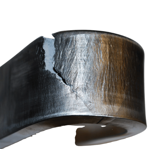
8 Weld Defects That Testing Is Designed to Catch
NDT techniques are not interchangeable; they are all specialized in detecting a certain sort of flaw at a certain location. Prior to identifying a suitable inspect method a fabricator must be aware of which types of discontinuity are expected for the particular process, material and joint shape, etcl! The following table details the eight types of fault encountered by the most structural steel Inspectors.
| Defect | Root Cause | Severity | Best Detection | AWS D1.1 Allowance |
|---|---|---|---|---|
| Cracks | Hydrogen, shrinkage, restraint | Critical | UT, PAUT, MT, PT | Zero tolerance — always reject |
| Lack of fusion (LOF) | Insufficient heat input, fast travel | High | UT, PAUT, RT | Not permitted |
| Incomplete penetration (IP) | Wrong parameters, tight root gap | High | RT, UT | Not permitted in CJP; limited in PJP |
| Porosity | Moisture, contamination, shielding gas loss | Moderate | RT (best), UT, VT (surface) | Max 6 mm cluster per 300 mm weld (static) |
| Undercut | Excess current, wrong electrode angle | Moderate | VT, weld gauge | Max 1 mm (static); max 0.25 mm (cyclic) |
| Slag inclusion | Poor inter-pass cleaning (SMAW/FCAW) | Moderate | RT, UT | Individual sizes limited by Table 9.1 |
| Overlap / cold lap | Low heat, fast travel, wrong angle | Moderate–High | VT, PT | Not permitted |
| Burn-through | Excess heat, thin material | Moderate | VT | Not permitted |
Engineering Note — Discontinuity vs Defect Discontinuity is defined as a discontinuity in the homogeneity of the weld metal, i.e. porosity, inclusion, undercut etc. A defect is a discontinuity outside the code acceptance criteria and should be repaired/rejected. Not every discontinuity is a defect.If the same inspector will say ‘indications found’, only after he will compare the indication with Table 9.1. (VT) or the UT acceptance chart of AWS D1.1 the defect is correctly identified. Structural steel: Hierarchy of severity: Cracks> lack of fusion> Incomplete penetration> Porosity> Undercut (within limits).
6 NDT Weld Testing Methods Compared (Visual, UT, PAUT, RT, PT, MT)
Different NDT methods use different physical principles that define their capability of detection, penetration depth and costs of operation. All six methods used in structural steel fabrication are compared below.
| Method | Defects Detected | Depth Capability | Relative Cost | Structural Steel Use |
|---|---|---|---|---|
| VT (Visual) | Surface only | Surface | Lowest | 100% mandatory; all joint types |
| UT (Ultrasonic) | Cracks, LOF, porosity, inclusions | Full thickness | Moderate | CJP groove welds; plate >5/16″ |
| PAUT (Phased Array UT) | Cracks, LOF, planar flaws; superior flaw sizing | Full thickness; 1–2 mm lateral resolution | Moderate–High | CJP welds 3/16″–8″ per D1.1:2020 Annex H |
| RT (Radiographic / X-ray) | Porosity, inclusions; good volumetric image | Full cross-section; permanent film record | High | Butt welds; thin-to-medium plate; pipe |
| PT (Liquid Penetrant) | Open surface cracks, porosity | Surface only | Low | All materials including non-magnetic (SS, Al) |
| MT (Magnetic Particle) | Surface and near-surface cracks | Surface + ~3 mm subsurface | Low–Moderate | Ferromagnetic carbon and low-alloy steel only |
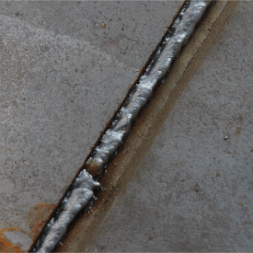
Is visual inspection of welds enough for structural steel?
For fillet welds under AWS D1.1 (statically loaded structures), simply using visual inpection alone will do – if every weld is within the dimensional and profile limits shown in table 9.1. But for complete joint penetration (CJP) groove welds, D1.1 mandates volumetric inspection – either UT, RT, or MT in specific situations. Why? Geometry. A planar lack-of-fusion or a tight cracking parallel to the weld line is a blind spot for the eye, but easily picked up by UT. An inspector in the AWS forum summarized it as: “100% visual inspection only becomes an 80% visual inspection because things can be missed.” VT is the gold standard, not the gold medal – for any CJP weld in structural steel.
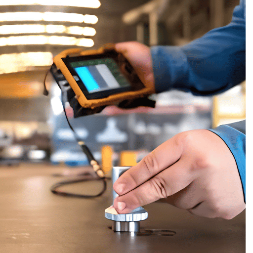
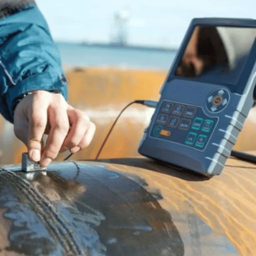
Ultrasonic Testing (UT) — The Standard for Thick Structural Steel
Conventional UT sends high frequency sound pulses (namely 2-5 MHz) into the weld from an angled transducer on the plate surface, with internal flaws producing a return echo. The phase and magnitude of the reflected signal reveal flaw size and depth. AWS D1.1 Part F specifies UT of 5/16 (8mm) to 8 (200mm) inch thickness CJP groove welds, and UT can detect flaws that 0.5mm wide. Because it does not need radiation safety protocols, UT is preferred for thick plate. It is simply very operator skill-dependent – the quality relies on the coder’s ability to interrogate the correct beam angles and respond from the A-scan display.
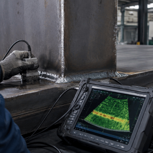
Phased Array Ultrasonic Testing (PAUT) — Higher Resolution, Permanent Record
PAUT utilises a multi-element array (minimum 16 elements under AWS D1.1 Annex H) that electronically scans the ultrasonic beam at multiple angles simultaneously – no manual rastering in conventional UT required. The procedure creates a 3D weld cross-section image, a permanent, encoded record similar to an X-ray film, and the scan resolution is only 1-2mm (versus 5-10mm in conventional UT). AWS D1.1 added PAUT approval with the 2015 D1.5 Bridge Welding Code, and in the 2020 D1.1 Structural Welding Code -Annex H – for 3/16 to 8 inch material.
“Phased array is widely accepted in industry standards including AWS D1.1 and AWS D1.5 which govern the inspection of structural welds” said Haworth. Focusing techniques – FMC (Full Matrix Capture) and TFM (Total Focusing Method) – are now applied along with PAUT where conventional sectorial scans cannot detect complex or atypically located flaws, however FMC/TFM are yet to be incorporated into D1.1 acceptance standards.
Radiographic Testing (RT / X-ray) — Full Cross-Section Visibility
RT – Radiography analyzes the weld by passing a beam of ionizing radiation (X-ray, gamma-ray, etc.) through it and recording a shadow image on a film or digital detector. It reveals defect volumetric information very well – porosity, slag, and lack of penetration. An RT indication shows as any darker area in the film. RT provides a permanent record that can be used as a court-record, and is easily interpreted by non-UT personnel. RT’s limited sensitivity to tight planar defects (cracks running in the plane of the beam), the need for radiation safety procedures (exclusion zone, license), and slower setup time than UT are conmanding factors. Of comparative note – a US DOT study radiographed and ultrasonically tested the same structural welds and determined that UT is most economical for planar defect detection, but RT images are often better for volumetric weld quality improvement.
Liquid Penetrant Testing (PT) — Surface Cracks on Any Material
PT – Penetrant analysis applies a liquid penetrant to the weld surface and then develops the indication through a series of steps including application of a special developer.This method can identify any surface cracking material regardless of the base material – a standard in detecting sharp notches or cracks in stainless steel, aluminium, and other nonmagnetic alloys; it makes PT the de facto standard for austenitic welds that cannot be inspected magnetically. On carbon steel structural welds it was about equal in sensitivity to open surface cracks like MT and faster to perform on ferromagnetic material. Any subsurface indications that do not path to the surface leave an inconclusive indication – a hard limit. When welds are not visually clear, where weld profile limits VT interpretation, PT can be used as an addition.
Magnetic Particle Testing (MT) — Near-Surface Sensitivity on Carbon Steel
MT – Magnetizes the weld zone, then applies iron powder – dry or wet. Discontinuities near the surface along the weld zone disturb the magnetic flux; the particles collect and form a visible indication. MT detects near-surface cracks reliably in about 3 mm of material, effectively making it faster and more sensitive to near-surface cracking than PT. Conditions for use are: ferromagnetic material, and at minimal 3 mm depth of indication from the surface. Unlike PT, function is restricted to ferromagnetic alloys – structural carbon steels and low alloys. MT finds use on fillet welds and welds with restrictively little access to allow UT scanning.
What is the most commonly used method of weld inspection?
The ‘traditional’ volumetric method: ultrasonic testing and phased array ultrasonics are the most popular NDTs on structural steel welds, especially groove welds above 10mm plate thickness. The most-performed method (because of AWS D1.1) is visual testing – but the visual method will only fully evaluate the weld surface. For a complete joint penetration weld the volumetric inspection method will be UT. RT is also often used on piping and thin-section welds where a permanent record is required.
Engineering Note — Detection Specifications UT: Can detect planar cracks ≥ 0.5 mm; calibrated against .060-inch side-drilled holes per AWS D1.1 procedure. RT: Best sensitivity for porosity ≥ 0.5% void fraction; less effective for tight planar cracks running parallel to the radiation beam. PAUT vs conventional UT: Lateral resolution 1–2 mm (PAUT) versus 5–10 mm (conventional UT). A 64-element PAUT probe captures 4,096 A-scans per scan pass, providing a full cross-sectional image rather than a point-by-point reading. MT: Near-surface detection to approximately 3 mm depth; sensitivity drops sharply below that threshold.
Destructive Weld Testing: When You Need It and What It Proves
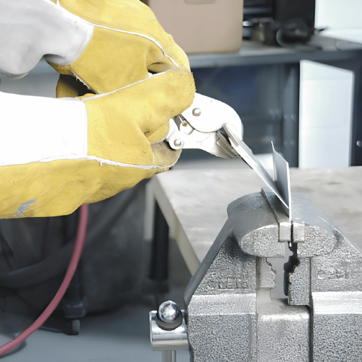
The destructive method: destructively tests (crushes or cuts) the welds in order to measure the physical properties that define the welds – tensile test, bend test, fusion, etc. Its use is limited to testing the WPS (Welding Procedure Specification) qualification. Once the procedure has been defined through DT, all welds performed to that WPS are qualified to be inspected nondestructively.
Destructive Testing — When to Use
- WPS qualification (PQR coupon testing)
- Welder performance qualification
- Procedure change re-qualification
- Production sampling on high-volume repetitive joints (per contract stipulation)
Destructive Testing — Limitations
- A weld destructive to weld – unusable for production joints
- Sample-based — no 100% coverage possible
- Reveals properties only at the tested location
- No replacement for NDT, it just qualifies the procedure an NDT will govern
| DT Method | What It Measures | When Required | Governing Code |
|---|---|---|---|
| Bend test | Ductility; fusion at root and cap | All WPS qualifications | AWS D1.1, ASME IX |
| Tensile test | Ultimate tensile strength vs base metal | Groove weld WPS qualification | AWS D1.1, ASME IX |
| Nick-break test | Internal soundness; fusion quality | Fillet weld and plug weld qualification | AWS D1.1 |
| Macroetch test | Weld profile, fusion, pass geometry | Fillet weld WPS; welder qualification | AWS D1.1, ISO 17639 |
The deliverable of successful DT sequence is a Procedure Qualification Record (PQR) – the proof that a certain set of welding variables results in welds that meet the code mechanical requirements. All production WPS have to have a valid PQR as reference. No qualified WPS, no documented proof, no assurance any NDT result is reproducible against a baseline.
Weld Testing Standards and Acceptance Criteria (AWS D1.1, ASME IX, ISO 3834)
Applicable weld testing code is not a matter of choice — it follows from the structure type, contract specification, and jurisdiction. Using the wrong code, or misapplying the right one, produces an inspection result that is not legally defensible. Four codes most relevant to structural steel fabrication are compared below.
| Standard | Industry / Scope | Key NDT Requirement | Frequency |
|---|---|---|---|
| AWS D1.1/D1.1M:2020 | Structural steel buildings, bridges, general fabrication (US) | 100% VT; UT or RT for CJP groove welds; PAUT permitted (Annex H) | VT: 100% of all welds; volumetric: per contract or 25% baseline |
| AWS D1.5 Bridge Welding Code | Highway bridges (US) | Stricter than D1.1; 100% UT on tension CJP welds; PAUT accepted since 2015 | 100% volumetric for tension members |
| ASME Section IX | Pressure vessels, boilers, piping (worldwide) | Governs WPS/PQR qualification; NDT requirements in Section V (RT, UT, MT, PT) | Per Section VIII or B31.3 construction code specification |
| ISO 3834 | Manufacturing quality system for fusion welding (international) | Quality management framework; mandates pre/during/post inspection records; WPS validation | Inspection at all three phases; documentation of every hold point |
Engineering Note — AWS D1.1 Visual Acceptance Limits (Table 9.1) Undercut: Maximum 1 mm depth for statically loaded structures; maximum 0.25 mm for cyclically loaded structures (bridges, crane runway beams). Groove weld reinforcement (cap height): Maximum 3 mm above the base metal surface for most joint configurations. Cracks: Zero tolerance — any crack in any location is an automatic reject and repair-required condition under D1.1, ASME VIII, and all other applicable codes. Surface porosity: Maximum cluster of 6 mm in any 300 mm of weld length (statically loaded); not permitted for cyclically loaded structures. These criteria apply to VT. Acceptance criteria for UT (amplitude based) are given in D1.1 Clause 8 and Tables 8.1-8.2.
Pro Tip — Confirm the Applicable Code Before Design Contract documents must specify the applicable code before fabrication commences – not be determined after-the-fact at the inspection stage. Code selection impacts joint design, preheat parameters, WPS scope qualification and NDT frequency. A rebuilder that qualifies WPS procedures per AWS D1.1 and then realizes that the customer requires ASME Section IX may need to re-qualify the procedures. Snap this and hold it in email confirmation at the bid stage.
How to Choose a Weld Testing Method: The 5-Factor Weld Test Selection Matrix
No single NDT method fits every structural steel application. Five factors determine the right selection: joint type, plate thickness, access availability, code requirements, and budget. Below, these factors map to method recommendations. Three scenario examples that follow show how the logic applies in practice.
| Factor | Option A | Option B | Option C |
|---|---|---|---|
| Joint type | Fillet weld | Groove weld (PJP) | Groove weld (CJP) |
| Plate thickness | < 10 mm | 10–40 mm | > 40 mm |
| Access constraint | Both sides accessible | One side accessible | Limited — confined space |
| Applicable code | No NDT specified | AWS D1.1 (standard) | AWS D1.5 or ASME IX (high criticality) |
| Budget priority | Lowest cost | Moderate cost | Prioritize detection accuracy |
| → Recommended method | VT + MT | UT (conventional) | PAUT or RT |
Scenario 1 – H-beam fillet welds, static load, AWS D1.1 specification: If X = fillet weld + plate <20 mm + static load + D1.1 code + cost sensitive budget Use VT + MT. Visual inspection offers a full two dimensional surface scan of the weldment, while MT contributes enhanced near-surface flaw detection at the weld root, which is also the startup site for fatigue on fillet welds. No volumetric testing is specified by the specification for fillet welds in this scenario.
Scenario 2 – CJP groove weld, 40 mm plate, AWS D1.1: If X = CJP groove weld + 40mm plate + D1.1 code + moderate budget Use UT. When the plate thickness is 40 mm, standard UT offers the advantage of full through-thickness coverage and a higher speed of execution (no IR exclusion zone) over radiography, as well as compliance with D1.1 acceptance criteria for groove welds. PAUT becomes a good enhancement if record of scan coverage is a contractual requirement.
Scenario 3 – Box column, CJP, bridge application, high cycle: If X = box column CJP + >40 mm plate + D1.5 code + bridge (cyclically loaded) + permanent record required Use PAUT. D1.5, because of the tension welds, demands a higher level of inspection scrutiny; PAUT provides 3D record coverage, 1-2 mm lateral resolution and greater speed of execution than conventional UT and is specifically approved in D1.5 Annex H.
Building a Weld QC System for Structural Steel Fabricators
Weld testing does not begin after the weld is complete. Effective Quality Control systems identify defect states before the first arc ever hits the weld joint. Studies over the past forty years show that the only way to reasonably eliminate NDT rejection of complex fabrication is to affect inspection through bake-in quality control: a 30-50% reduction in NDT rejection is possible throughFit-Up inspection alone. The three-phase roadmap below visualizes what the systems check and when.
① PRE-WELD
- WPS at workstation, current revision
- Welder WPQ certificate valid and applicable
- Base material MTR traced to heat number
- Filler metal classification matches WPS
- Joint prep: bevel angle, root face, root gap measured
- Hi-lo alignment ≤ 3 mm (D1.1 maximum)
- Joint surfaces clean within 25 mm of weld toe
- Preheat temperature confirmed (calibrated thermometer)
- ITP hold points set; inspection log open
② DURING WELDING
- Amperage, voltage, travel speed vs WPS range
- Shielding gas type and flow rate confirmed
- Each pass visually checked before next is deposited
- Inter-pass slag and oxide fully removed
- Interpass temperature measured and recorded
- Pass sequence follows WPS or procedure detail
- Backgouged surface inspected before second-side welding
- Arc strikes outside weld zone: immediate stop-work
③ POST-WELD
- VT mandatory first (min 500 lux lighting)
- Undercut, cap height, profile measured with weld gauge
- Dimensional accuracy vs drawing tolerances
- NDT per ITP: UT/PAUT, RT, MT, or PT as required
- NDT reports signed by Level II or III examiner
- PWHT time-temperature chart archived (if required)
- Weld traveller complete; every field signed
- Non-conformances documented and dispositioned before release
Tip — Digital Weld Traceability Paper-based weld “travelers” have actually proven effective – until one gets lost, rolled in the muddy wheelbarrow, or misread in an audit. Digital weld log systems (tablet-based QC apps or integrated ERP inspection modules) make this a non-issue: a field can’t be cleared until its preceding field is populated. Bridge and high seismic structural steel project specs now increasingly specify digital traceability records for every weld joint to WPS, welder ID, NDT result, and inspector certification number. Traceable for life.
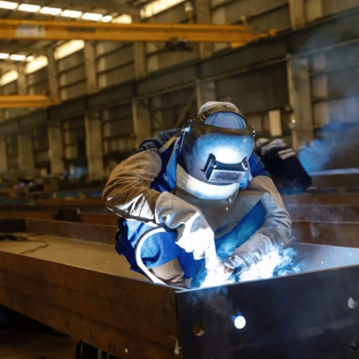
How Robotic Welding Systems Affect NDT Pass Rates

The connection between weld consistency and NDT pass rate is direct. Manual welding introduces arc-on time variability. A skilled welder averages around 25-35% arc-on time in a shift (regardless of arc idling, repositioning, retooling, rest periods, or fit up adjustments). Weld travel speed oscillates, interpass temperature management relies on individual judgment, and welder fatigue affects the quality of late-shift passes. Each of those factors is a defect introduction pathway that UT and RT field discovery seek to prevent.
Robotic welding removes those factors. Automated robotic systems reproduce identical voltage, amperage, travel speed, and torch incline from pass 1 through pass 12,040. Such control is clearly recordable with NDT data. At a bridge fabrication shop utilizing Zhouxiang’s intelligent steel structure welding system, sole-developed NDT pass rate on groove welds jumped from 82% to 97%. Arc-on duty cycles more than doubled, and the equivalent number of productive weld hours per shift increased with it.
Key Performance Data — Robotic vs Manual Welding
82% → 97%
UT pass rate (Zhouxiang bridge fabricator case)
85%
Arc-on duty cycle (robotic) vs 25–35% manual
0.5–3%
Robotic defect rate vs 5–10% manual (industry data)
±0.05 mm
Positional accuracy (Zhouxiang system specification)
Pro Tip — Digital Twin and 100% Weld Traceability Digitized robotic welding systems with digital twin modules monitor every parameter of every weld pass–arc voltage, wire speed, travel rate, torch angle–in real time (as ratio to the joint ID number).Such data is the 100% traceability record project specifications demand. When an NDT indication occurs, B1 inspectors can query the digital record of that joint for any welding parameter immediately, instead of tracking down the stain in the paper traveler. This is the real-world capability linkage defining robotics and inspection efficiency.
For structural steel fabricators benchmarking the high-production NDT challenge of high-volume overhead gantries, H-beams, box girders, and portal frames, the ROI question is not simply speed. It is rework cost. At 1-2% NDT rejection, most shops make money. At 10%, rework cost outweighs the labor efficiency of a manually weld shop entirely. A robotic structural steel welding system tackles the consistency variable NDT measures to compensate for.
Related Zhouxiang resources: structural steel welding robot solutions | robotic vs manual weld quality comparison | how does robotic welding technology work | gantry welding robot workstation | how does a gantry welding robot work | cantilever welding robot for steel fabrication
Weld Testing Trends: What’s Changing Through 2030

The NDT and inspection market is poised for 8.3% CAGR growth, up from $14.99 billion in 2025 to a forecasted $22.34 billion by 2030 (MarketsandMarkets). Widespread growth in that US market will manifest in five patterns affecting structural steel weld inspection.
- PAUT replacing conventional UT on thick plate. Implementation of PAUT was driven by AWS D1.1:2020 codification (Annex H) [a]. The permanent encoded scan record, faster coverage, and 3D flaw imaging help make conventional UT progressively difficult to justify for CJP groove welds above 20 mm.
- Digital radiography (DR) replacing film RT. Film RT, slow and a source of negative chemical and metal waste, can be replaced with digital detectors delivering the same volumetric image in real time, with no film archiving cost and immediate electronic delivery of records to the design team.
- AI-assisted defect detection. Machine learning models trained on RT and PAUT scan libraries are deployed to mark likely indications for human review – reducing the risk of false-negative interpretation on high-volume inspection programs. Early results show detection consistent with experienced Level II inspectors on normal defect types.
- 100% traceability requirements expanding. Increasingly strict bridge codes and seismic zone structural specifications require digital weld records linking every joint to its inspection result, inspector ID, and welding parameters – a feature only robotic systems with integrated data logging can provide without manual data entry overhead.
- FMC/TFM as upgrades to PAUT. Full Matrix Capture and Total Focusing Method allow inspector-level flaw characterization beyond what standard PAUT sectorial scans can resolve. Although still not acceptable under AWS D1.1, they are used on complex weld geometries where sectorial scans are blind to off-axis or transverse flaws.
For fabricators deploying new NDT equipment and methodology today, the bottom line is clear: PAUT and digital radiography are future-proof in structural steel. Film RT and conventional UT still meet code, but efficiency, record quality, and future specification compliance will continue diverging each code cycle. For overview, see: welding robot maintenance and robotic welding ROI analysis in the larger automation investment.
FAQ — Weld Testing Questions from Steel Fabricators
How do you test a weld?
Show answer
Begin with VT [b], required under all structural codes; then for complete JIG, employ UT or RT in the event of hidden internal flaws. [c] For welder qualification, use destructive tests on samples before production.
What is the most commonly used method of weld inspection?
Show answer
Visual testing (VT) is performed on 100% of all welds on all structural steel work – making it the most performed in actual raw coverage terms. Ultrasonic testing (UT) is the most specified volumetric inspection method for complete joint penetration groove welds on all North American structural steel fabrication work. PAUT is slowly replacing conventional UT at many shops after it became part of AWS D1.1:2020.
What are the five standard NDT methods for welding?
Show answer
The five main NDT methods employed in structural steel weld inspection are: 1) Visual Testing (VT), 2) Ultrasonic Testing (UT), including Phased Array UT (PAUT), 3) Radiographic Testing (RT), 4) Magnetic Particle Testing (MT), and 5) Liquid Penetrant Testing (PT). Time of Flight Diffraction (TOFD) and Eddy Current Testing (ET) are also used on occasion but are less prevalent in general structural steel fabrication.
What is the difference between destructive and non-destructive weld testing?
Show answer
Non-destructive testing (NDT) refers to inspecting a weld without melting or cutting – the weld remains in service after testing. This can include VT, UT, RT, MT, and PT. Destructive testing involves physically breaking or cutting the weld to determine properties such as ultimate tensile strength and ductility. Destructive tests are exclusively performed to justify a Welding Procedure Specification (WPS) on test coupons – not production welds.
Which code governs weld testing for structural steel in the US?
Show answer
AWS D1.1/D1.1M:2020, Structural Welding Code – Steel, is the primary document controlling weld inspection of structural steel buildings and fabricated members in the US. AWS D1.5 Rules for the construction of highway bridges are more restrictive. ASME Section IX is used to qualify WPS/PQR on pressure vessels and piping. The required code should be specified in the contract scope of work prior to fabrication.
Can visual inspection alone pass welds for structural steel projects?
Show answer
For fillet welds made to AWS D1.1 (statically loaded), the bare minimum before considering other volumetric methods, traditional VT can prove sufficient if the weld appears to meet all Table 9.1 acceptance criteria. Complete joint penetration (CJP) groove welds must still be subjected to volumetric inspection per AWS requirements – either UT, RT or for some situations MT. VT cannot see internal flaws like lack of fusion or internal porosity. It is the minimum for CJP welds, not the entire inspection program, AWS D1.1 Article 9 requirements apply. Refer also to: welding robot safety guidelines.
How does robotic welding affect weld testing requirements?
Show answer
Use of a robotic welding system does not remove the need for code mandated weld inspection – the required frequency does not change. What it does alter is the NDT result. Because automated welders tend to match your programmed parameters (arc length, voltage, torch angle, travel speed, power control) they create consistent welding parameters which produce consistently lower defect levels – leading to a reduction in repairs after NDT. One customer moving to robotic welding in bridge work reported an increase in UT pass rate from 82% to 97%. Fewer repairs lead to less time spent on NDT checking in the field. Refer also to: welding robot safety practices.
What is a Welding Procedure Specification (WPS) and why does it matter?
Show answer
A Welding Procedure Specification (WPS) is a documented set of instructions that control a weld – including base metal, filler metal, fit-up geometry, preheat, amperage, travel speed, and more. Every welder follows a WPS at work. The WPS must be qualified using destructive testing (creating a Procedure Qualification Record, or PQR) before the WPS can be used on production welds. AWS D1.1 mandates that welding to a non-qualified WPS (existing or non-applicable) invalidates NDT test results – every weld must be retested.
Our Perspective This article was authored by Zhouxiang, a maker of robotic welding systems sold into steel fabricators. From a commercial perspective we are promoted by automated welding – we feel robotic systems provide higher quality welds and lower rejection rates and our customer data1 to that effect reinforces this opinion. The NDT procedure descriptions, code references and acceptance criteria contained in this article are extracted from publicly available standards and practitioner sources and are not presented to reflect that position.Please check any code references against the applicable edition of the relevant standard for your project/ location.