Get in Touch with Zhouxiang

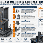
H-Beam Welding Automation: Stiffener, Base Plate, and Corbel Sequencing
Contents
show
Structural steel fabricators automating their H-beam lines have a similar observation: their first full automated shift outputs more parts than the entire prior week of manual welding. That productivity surge is a result of cutting out the lost and unseen time-fit-up rework, manual welders’ varied levels of fatigue, flu×es being scraped off-not the fact that they are running faster machines. In any kind of production, if you need to make repeatable fillet welds over the same joint with the same materials on the same profile-whether they are four webs-to-flange welds on every single H-beam, or identical spot welds across the front doors of cars-it’s among the highest ROI opportunities in manufacturing automation. This guide e×plores H beam welding automation from the three perspectives that matter most: How a H-beam fabrication line is set up; which level of H-beam automation fits your part mix; how SAW parameters get the job done on repeated joints; and what your 2025 ROI on these systems really look like.
What Is H-Beam Welding Automation?
Automating H-beam welding means deploying mechanized or robotic welding technology to weld the web plate of a structural steel beam to the two flange plates, creating a finished I-beam or H-beam profile — reducing dependence on manual arc welding or augmenting it. This automation can range from automated pull-through torches that still require an operator to position each part (Level 1), to entirely automated cells that will locate the part for the process without any human in the loop from part to part (Level 4).
There is a clear structural rationale for automation, beginning with a key geometric property of any H-beam or I-beam: just four fillet welds connect the web and flanges, consistently. This identical profile is precisely what automated welding excels at producing: Structural fabricators find their automated H beam production lines deliver 3 to five times the output per hour, or even per shift, compared with identical manual welding applications, due to vastly improved arc-on time (automated systems hold anywhere between 60- and 80-percent arc-on, versus 15- and 25-percent average for manually welding where a worker has to take breaks, set up, or verify. This dramatic gain in production efficiency explains why H-beam automation commonly pays back within 8–22 months even at moderate output volumes.
Quick Specs: Standard H-Beam Welding Range
| Parameter | Standard Range | Heavy-Duty Range |
|---|---|---|
| Web height | 200–1,000 mm | 1,000–2,000 mm |
| Flange width | 100–400 mm | 400–800 mm |
| Web/flange thickness | 6–18 mm | 18–40 mm |
| Beam length | 5–12 m | 12–18 m |
| Automated throughput | 18–30 beams/shift | 8–18 beams/shift |
What Is an H-Beam Fabrication Machine?
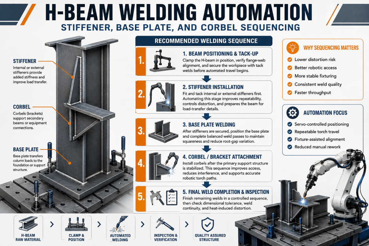
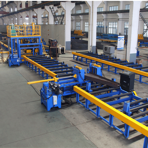
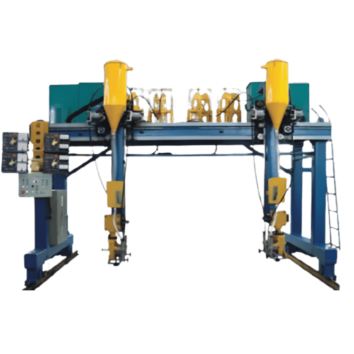
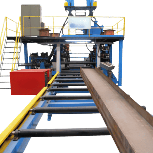
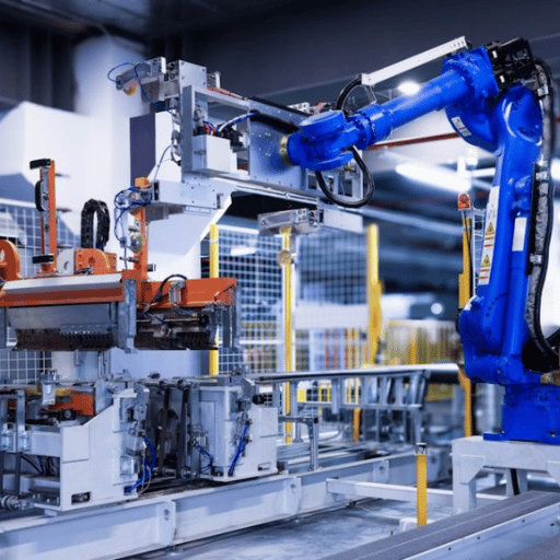
An H beam welding machine — also referred to as a beam fabrication line or automated I-beam welding system — integrates three coordinated stations used across steel fabrication shops: an assembly welding station where two flanges and a web are positioned and tack-welded into an H profile, a SAW pull-through machine completing all four web-to-flange fillet welds automatically, and a welding straightening unit that corrects angular distortion from weld-induced heat. These systems range from 200 mm web height to 2,000 mm (8 to 80”), flange widths from 100 to 600 mm (4 to 24”), with beam lengths of 5 to 18 meters (15 to 60 feet). An average automated beam line will replace 3 to 5 operators depending on beam size and output volume.
Inside the 3-Station H-Beam Production Line: Assembly, Welding, Straightening
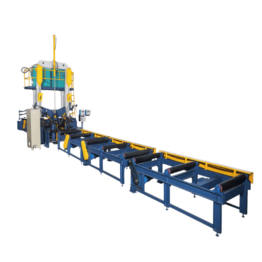
Automated beam welding lines for H-beam production link three sequential stations via motorized roller conveyors, passing the raw product continuously from one stage to the next. They comprise a beam assembly station where plates are positioned and tack-welded, the beam SAW welder performing the longitudinal fillet welds, and the beam straightening machine maintaining overall dimensional shape after welding. The physical separation of these three processes into discrete stations is what enables each to be optimized independently — the single most important concept most automation buyers overlook. Most concentrate on the SAW welder alone, setting themselves up with a well-built welder they cannot keep fed with product. Discover how our wide range of automated structural welding configurations for different beam product volumes can benefit your business.
| Station | Function | Key Parameter | Output |
|---|---|---|---|
| 1 — Assembly Machine | Hydraulic clamps position web plate vertically between two horizontal flanges; automatic tack welding secures the T-joint at set pitch intervals | Tack pitch: 300–500 mm; fit-up gap ≤1 mm | Tack-welded H-profile ready for SAW |
| 2 — SAW Welding Machine | Pull-through welder feeds the beam through dual SAW torches, completing all four longitudinal fillet welds automatically; flux is deposited and recovered continuously | Travel speed: 400–2,000 mm/min; current: 500–1,250 A | Fully welded H-beam (may have angular distortion) |
| 3 — Straightening Machine | Hydraulic roller-straightener applies controlled pressure to correct welding-induced angular distortion (flange twist) to within tolerance | Correction tolerance: ≤L/1,000 (typically ≤3 mm/m) | Finished H-beam to dimensional specification |
Engineering Note
The tolerance on the web plate to flange T-joint fit up is 1mm gap to provide consistent penetration in a submerged arc welding operation (SAW). If the gap exceeds 1.5mm there is flux fallthrough, fill defects and instability of the arc-which is the number one source of rework on an H-beam line. This fit-up challenge is addressed in the AWS D1.1 requirement, Clause 5.22 – fit-up requirements for T-joints.
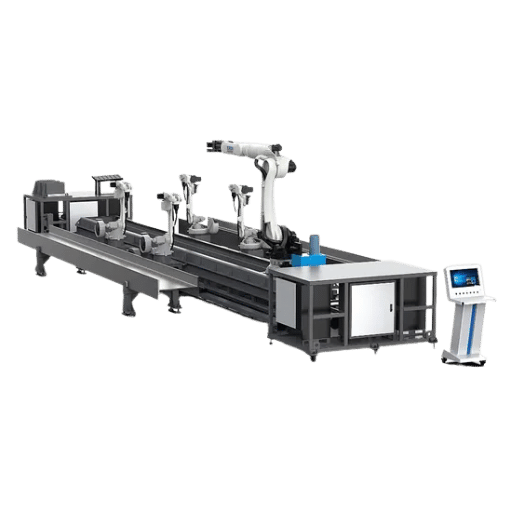
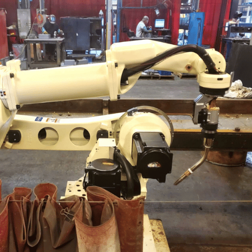
Four Levels of Welding Robot Programming for H-Beam Fabrication
Much of the conversation in the welding industry about welding automation paints a dichotomy — the choice is either “manual” or “robotic.” However, there is a four-level system for programming robotic welding, and most structural fabricators are at either Level 1 or Level 2 of the progression. Each level represents a distinct welding workflow, from manual teach-pendant control all the way to fully autonomous systems where a dedicated controller drives the robot with zero operator input between parts. Choosing the wrong level — “under-automated” (process bottlenecks) or “over-automated” (CapEx on unused capability) — is the most expensive mistake in any welding automation project.
| Level | Programming Method | Setup Time/Beam | Operator Input | Curved Beams | Best For |
|---|---|---|---|---|---|
| Level 1 | Manual teach pendant — operator guides robot arm to each weld point | 30–90 min | High — full-time operator | No | Low volume, high-variation parts |
| Level 2 | Assisted programming — parametric templates, operator selects beam size and weld type from menu | 5–15 min | Moderate — monitors, adjusts | No | Medium volume, standard H-beam sizes |
| Level 3 | Offline programming (OLP) — weld paths generated from CAD model on a PC; small touch-ups required at machine | 1–5 min touch-up | Low — verification only | Limited | High volume, consistent beam catalog |
| Level 4 | Autonomous — 3D vision scans actual beam geometry; robot self-programs and welds without human intervention between parts | Zero | Minimal — exception handling | Yes — via 3D adaptive scan | Mixed sizes, curved, high-variation geometry |
“The robot ‘looks’ at the workpiece in front of it and welds without human involvement whatsoever.”
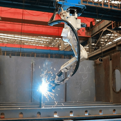
Today, robotic welding systems for H-beams are available across all four levels of automation.Most structural steel fabricators are currently operating with systems at either Level 1 or Level 2 of this four-level spectrum;However,Level 4 technology that made its debut several years ago in early-adopter applications is making the leap to mainstream availability in 2025-2026.
What Is the Difference Between Offline Programming and Autonomous Welding for Structural Beams?
Offline programming (Level 3) requires CAD software to generate weld paths before a beam is ever positioned at the robot workstation. While CAD programming offers accuracy, it assumes a perfect physical replica of the beam as drawn — any fit-up deviation will require manual touch-ups at the machine. The autonomous welding capability of Level 4 eliminates this assumption: a 3D structured-light scanner reads the beam’s actual contour in real time, and the robot dynamically corrects its path as it welds. This eliminates pre-programming time between beams and allows for the automatic welding of variable or curved beam profiles without fixture modifications.
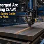
Submerged Arc Welding (SAW): The Core Technology in H-Beam Production Lines
Submerged Arc Welding dominates H-beam fabrication for three reasons no other process matches at scale: deposit rates of up to 45 kg (almost 100 lbs.) per hour (vs. 1–5 kg/hr for MIG/MAG), a slag shield that protects operators from spatter and UV light and travel speeds on a standard web to flange joint, of 400 to 2,000mm (16 – 80 inches) per minute. Because the welding arc is submerged under granular flux — which gives submerged arc welding its name — the unused flux is automatically recovered and recycled, reducing consumable costs. Read the full technical breakdown in our dedicated submerged arc welding guide.
| Wire Diameter | Current Range | Voltage | Typical Application |
|---|---|---|---|
| 2.4 mm (3/32″) | 250–700 A | 22–37 V | Thin flanges, tack-seal welds (6–12 mm) |
| 3.2 mm (1/8″) — most common | 300–900 A | 23–37 V | Standard H-beam web-flange fillet (10–25 mm) |
| 4.0 mm (5/32″) | 400–900 A | 24–40 V | Medium-heavy web plates (12–25 mm) |
| 6.4 mm (1/4″) | 700–1,600 A | 30–38 V | Heavy flanges and thick web plates (25–40 mm) |
Engineering Note — Electrode Selection (AWS A5.17)
EM12K (low-manganese, high silicon) is the standard electrode used for structural SAW of H-beams, which produces a low bead with excellent toughness at -30 °C over the entire thickness range for web, flange, and beam sizes. When higher yield strength deposited metals are needed, for structural or pressure vessel (bridge-grade) applications, EM13K is the standard choice.Flux classification under AWS A5.17 neutral flux (EM12K with F7A2 prefix designation), provides consistent quality multideposit welding with little risk of manganese build up.
Tip: A close, precise, fit for web-plates with an thickness down to 18mm; Eliminates the need for a bevel in your process, shaving 15-20 minutes per beam off machining time.
Robotic Welding vs. Manual Welding for H-Beams: What the Data Shows
The comparison between robotic and manual welding is often framed as a quality argument. The real case is an efficiency and consistency argument. A skilled manual welder doesn’t produce lower-quality welds — it’s the variance that hurts production: operator fatigue across a shift, repositioning downtime, and fit-up tolerance inconsistency combine to make manual H-beam throughput unpredictable.
Robotic Advantages
- High efficiency arc-on time: 60–80% of shift (vs. 15–25% manual)
- Reliability: defect rate 2–3% vs. 8–12% for manual
- Cycle time consistency: ±1% vs. ±15–20% manual variance
- 1 operator monitors 18–30 beams/shift
- 24/7 unattended capable (Level 3+)
Limitations
- High upfront capital (>$75K+)
- Requires fit-up precision ≤1 mm gap
- Level 1–2: cannot adapt to beam variation
- Software setup learning curve (2–8 weeks)
- Skilled technician needed for maintenance
Common Misconception
“Robotic welding systems can’t handle mixed beam sizes.” This is true for Level 1–2 systems, which require reprogramming for each new beam size. Level 4 autonomous systems with 3D vision directly refute this limitation — the robot scans each beam’s actual geometry and self-adjusts, handling mixed sizes and even curved beam profiles without any programming change between parts.
Industry data point: A bridge component fabricator in North America switching to autonomous robotic welding recorded a 2.7× increase in weld metres per operator per shift, with UT first-pass acceptance rate reaching 97%. For a structural fabrication shop running 3 manual welders producing 8 beams per shift, that trajectory — moving to 1 operator monitoring 22+ beams per shift with consistent weld quality — represents the realistic payback engine for automation investment. See our detailed robotic welding ROI calculation guide to model your specific numbers.
ROI of H-Beam Welding Automation: Cost Benchmarks and Payback Analysis
Automation ROI for H-beam lines flows from two sources: labor cost reduction and throughput increase. The payback period formula is direct — total system cost divided by annual net benefit. What varies by shop is the loaded labor rate and the throughput multiplier the automation level delivers. A key advantage of modern H-beam automation machinery is that it is scalable: most manufacturers offer modular configurations that allow you to start with a semi-auto SAW station and expand to a full 3-station line as production volumes grow. This staged approach lets you reduce upfront capital risk while still achieving the throughput gains the market demands — without replacing core equipment. See our full robotic welding ROI calculation guide for a worked example.
Payback Period Formula
Payback (months) = Total System Cost ÷ (Monthly Labor Savings + Monthly Production Gain)
Example: A $200,000 semi-auto SAW line replacing 2 welders at $75,000/year loaded cost each = $150,000/year savings. Add $50,000/year in additional production capacity. Total annual benefit: $200,000. Payback: 12 months.
8–22
months payback (typical structural steel line)
3–5×
throughput increase vs. manual welding
$75K–$1M+
system cost range (cobot to full gantry line)
Payback Period Formula
Example: A $200,000 semi-auto SAW line replacing two manual welders costs $150,000/year (loaded). This system improves throughput from the $75,000/year with the manual welders and delivers a savings of that difference, plus $50,000/year in additional capacity (7% increase). The annual benefit to the organization is $200,000.
Based on the Total System Cost above, the payback is 12 months.
Costs used for 2024-2025 reflect market data ranges.
Actual costs vary greatly depending on configuration, desired automation level and installation requirements. Get a quote for your specific configuration.
| System Type | Automation Level | Approx. Cost (USD) | Typical Payback |
|---|---|---|---|
| Cobot welding package | Level 1–2 | $40,000–$75,000 | 6–12 months |
| Standard 3-station H-beam line (semi-auto) | Level 2 | $150,000–$400,000 | 12–22 months |
| Full-auto CNC H-beam line | Level 3 | $400,000–$700,000 | 18–30 months |
| Robotic gantry cell with 3D vision | Level 4 | $700,000–$1,200,000+ | 24–36 months |
You Need to Know These Variables When Choosing an H-Beam Welding Line configuration The choice of your line hinges on two primary factors: your production volume requirements and the variety of beam sizes you must handle. An under-spec’d line is one that you’ll outgrow and be out of capacity in 18 months. An over-spec’d line carries the capital weight that you’ll never see a return on your investment.
How to Configure Your H-Beam Welding Line: A Structural Fabricator’s Selection Guide
Selecting the right H-beam welding line requires matching three variables to your production reality: output volume, beam size variation, and available floor space. A compact cobot welding cell suits flexible small-batch shops running fewer than 10 beams per day; a full-auto multi-station SAW line suits heavy fabrication environments producing 30+ beams per shift. Use the framework below to match system type to your operation:
| Daily Volume | Beam Size Variation | Recommended Configuration | Level |
|---|---|---|---|
| <10 beams/day | Standard sizes, low variation | Semi-auto SAW line + manual assembly | Level 2 |
| 10–30 beams/day | Mixed sizes, moderate variation | Full 3-station CNC H-beam line, offline programming | Level 3 |
| >30 beams/day | Standard catalog sizes | High-speed full-auto SAW line with automated conveyor | Level 3+ |
| Any volume | High variation OR curved beams | Gantry robot workstation with 3D vision scanning | Level 4 |
Pre-Quote Checklist — Have These Numbers Ready
- Maximum flange width required (Also determined the size of machine to fabricate your beams)
- Maximum web and flange plate thickness (Determines the minimum SAW current capacity – not selecting enough current is a common cause of rework)
- Longest beam in your catalog (Determines your line’s length and its overall footprint)
- Daily/weekly beam count target (defines automation level justification)
- What percentage of your beam mix involves non-standard or curved profiles (This can be an indicator of the need for a Level 4 robotic welder.)
- 3-phase power supply available (standard lines require 380V/50Hz, approximately 125 kW per line)
Configuration Warning
One of the most critical specification errors that will cause frustration with your beam line (and eventually rework) is selecting a SAW welder with less current than needed for the heaviest plate you will be welding. If you need 1,000 amps but purchase an 800 amp welder, you will have to make multiple passes to complete the weld, effectively negating many of the efficiencies that automation offers. Zegbrk_0013.
For projects in steel structure welding robot solutions – including gantry type robotic cell for hybrid/large format H-Beam applications – get in touch with a systems integrator that can model your beam catalog vs. your cycle times before they spec hardware.
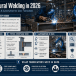
H-Beam Welding Automation Trends: AI Vision, Cobots & the Digital Thread (2025–2026)
Market Overview The structural steel welding robot market was valued at $3.11 billion in 2024, and is forecast to reach $7.13 billion by 2032 at a CAGR of 13%, the fastest pace across any manufacturing robot category.
The IFR’s World Robotics 2025 report also indicates 542,000 industrial robots were installed in 2024 with total installations across all industries standing at 4,664,000 units globally. Four major shifts are changing what’s possible in H-Beam welding:
- Autonomous Offline Programming Hits Mainstream(2025-2026): Level 4 welding systems available from vendors like AGT Robotics and Path Robotics are directly reading detailing software model data and welding without human teach programming, “freeing” programming to become the “bottleneck solver” that will let smaller shops easily attain Level 3+ levels.
- Structural Fabrication Adopts the Collaborative Robot: 10.5% of all new industrial robot installations were cobots in 2023.If your shops produce fewer than 10 beams per day, then there is not a faster pathway to ROI from welding automation than a robotic cell utilizing cobots ($40K-$75K).
- 3D Vision Eliminates Fixture-And-Teach: Light projected between 100Hz-500Hz by structured-light cameras and measurig the seam joint in x/y dimensions within .1- to .3mm lateral accuracy enables robotic adaption of the tool path irrespective of beam/fitup variation (Level 4 key enabler for structural fabrication).
- The Digital Thread connects Detailing Software to the Weld Cell: Detailing CAD software such as Tekla Structures and Revit is integrating to automated weld cells, “flowing” seam data directly from model — no re-input required, minimizing translation errors and paving the way for single-piece-flow.
- Fiber Laser Pre-Processing Feeds Directly into Beam Lines: The cutting process for web and flange plates is moving to integrated fiber laser cutting cells positioned upstream of the H-beam assembly station. This eliminates inter-process material handling and enables continuous steel structure production — from flat plate through cutting, assembly welding, SAW, and straightening — in a single uninterrupted workflow.
Action Tip for 2025
If your shop is operating at level 1-2, the high return on investment pilot upgrade move is towards robotic parametric template welding (level 2 3), instead of toward vision equipment. The gains from solving that bottleneck alone will often deliver 15-25% higher throughput for substantially lower CapEx.
Will Robots Replace Human Welders in Structural Fabrication?
Will Robots replace welders?
No. Even in Level 4 autonomous welding, human welding engineers will be needed to supervise robotic applications; to verify welding procedures (WPS) and NDT results. Instead, they become quality control overseers with skills more in demand, not obsolete, on an automated beam welding line rather than just laying beads as is shown here on this YouTube post describing automated, 75’ beam welding with AI vision: “The robot doesn’t have it entirely…There’s AT least one dedicated welding engineer for a line like that.”
Across fabrication shops adopting Level 3+ automation, the workforce pattern that emerges is consistent: headcount typically drops from five manual welders to two robot supervisors per shift, but those roles command higher wages and increasingly require AWS Certified Welding Inspector (CWI) credentials. AWS D1.1 Structural Welding Code mandates certified inspector sign-off regardless of automation level — a robot cannot self-certify a weld joint. Shops that transition successfully usually begin cross-training their best manual welders three to six months before installation, pairing them with the vendor’s commissioning team. Operators must learn to read welding procedure specifications (WPS), judge fit-up tolerances, and recognise when seam-tracking wanders off the joint. Those skills are not disappearing — they are the quality gate that keeps automated structural fabrication safe and code-compliant.
Frequently Asked Questions
What is the difference between H-beam and I-beam welding automation requirements?
H-beam flanges are significantly wider than those of I-beams (European IPE profiles), which affects two automation parameters: flux containment width and torch positioning angle. H-beams demand a wider flux bed support and more aggressive torch inclination to avoid overflow at the flange tips. They also result in greater heat input per length, meaning the straightening unit is even more essential in an H-beam line, whereas a line for I-beams might even be able to operate without it.
Can automated H-beam welding machines handle curved beams?
Typical Level 1-3 H-beam welding machines work on straight beams. Level 4 of autonomous robot work cells is needed for automated fabrication of curved and cambered H beams – for application on long-span roofs and bridges. The system’s 3D adaptive scanning follows actual curve geometry, making real-time, real curve, path adjustments to the torch head movement, instead of blindly traveling along an idealized path.
This dynamic adjustment overcomes challenges to weld consistency caused by a curved beam’s changing joints and can swing specification to Level 4 gantry robot solutions when working curves.
What welding process is most common in H-beam production lines — SAW or MIG/MAG?
Submerged arc welding (SAW) is extensively employed for the majority of primary web-to-flange fillet welds on H-beam production lines due to its unparalleled combination of deposition rates (over 45 kg/hr) and lack of spatter,which makes it the most cost-effective solution for the long continuous welds required for the production of the longitudinally produced H-beam. MIG/MAG (GMAW) is typically only seen as a tacked attachment at the fabrication / assembly stage, or to add in any finish welds or connection plates after the main production line. Some smaller systems based on cobots employ a total GMAW solution accepting the poorer process economy on these long welds for the cheaper equipment set and the improved job range flexibility for a small volume, wide-range producer.
How long does it take to commission a new H-beam welding line?
Basic 3 station semi-automatic H-beam lines commonly install in 8-16 weeks from order confirmation to final job on board including factory acceptance testing (FAT), transport, foundation preparation, electrical installation, and operator training. 3D vision fully automatic robotic cells with tailored fixtures typically have lead times of 16-24 weeks. The major lead time dependent factor is availability of the machine space on site (foundation, utilities), lead time for manufacture of special tools and complexity of interface with any third-party controls. A level 3+ system often will require 2-4 weeks training (operators, maintenance) before achieving full production rates.
What is an H-beam fabrication machine?
H beam fabrication machine H beam fabrication line is one production line for fabricating & assembling H shaped section steel parts with a web section (vertical) and two section (horizontal). A typical H section production line includes one H section assy machine (assembling, tack welding 3 pieces of flat bar into an H shape), one submerged arc welding machine (for welding 4 sides automatically of the two section and the one vertical piece), one correcting machine (straightening machine for correcting angular distortion after welding). Standard production range of the line is H section with web section 200-2000mm, flange section 100-600mm, H beam length 5-18m, and the production quantity can be 8-30 pieces/shift with full auto or semi-auto lines.
Reviewed by Zhouxiang Engineering Team | More than 15 years of design and implementation experience of structural steel welding automation systems for fabrication facilities in Asia, Europe, and North America.
Sources: IFR World Robotics 2025 Report; The Fabricator, March 2024; TWI Global SAW Consumables Technical Knowledge; IJRASET 2024 SAW Parameters Study (DOI: 10.22214/ijraset.2024.64851); Miller Electric SAW Technical Guide; Intel Market Research Steel Structure Welding Robot Market 2024.
Disclaimer: This guide was compiled by Zhouxiang, a manufacturer of automation systems for structural steel fabricators.
We reference independent third-party publications when we present market data. Price ranges refer to the 2024-2025 market data, and prices vary depending on manufacturer and options.