Get in Touch with Zhouxiang

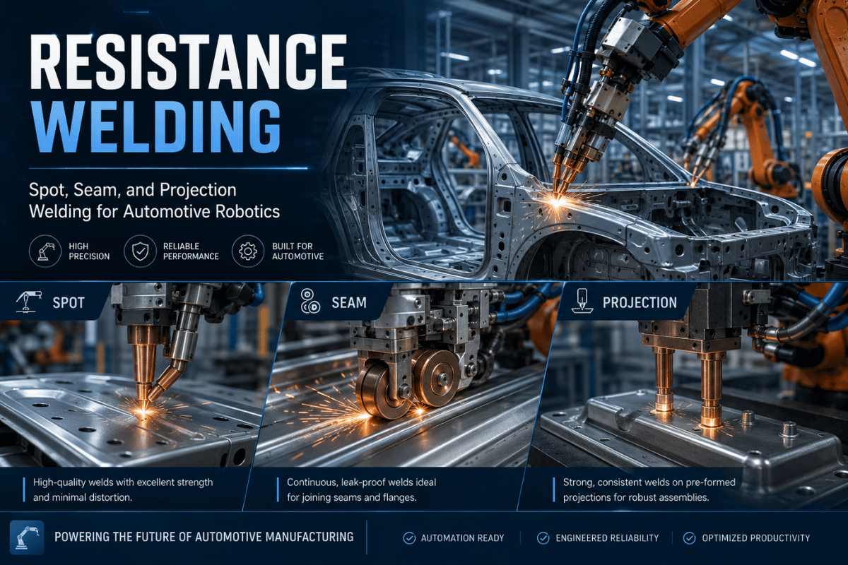
Resistance Welding: Spot, Seam, and Projection Welding for Automotive Robotics
Contents
show
Resistance welding is the fastest, cleanest way to join metal sheets at scale – no filler rod, no shielding gas, and no open arc. Joule heating — the same principle that powers a spot welder on an automotive body line — also drives the seam welder on your HVAC duct and the projection welder pressing nuts into sheet metal brackets. This primer e×plains the full resistance welding process, from the physics to the five process types, the parameters that influence weld quality, the materials that respond best (and worst), the capabilities of robotic versus manual machines, and where the technology heads through ²0²6.
What Is Resistance Welding? The Physics Behind the Process
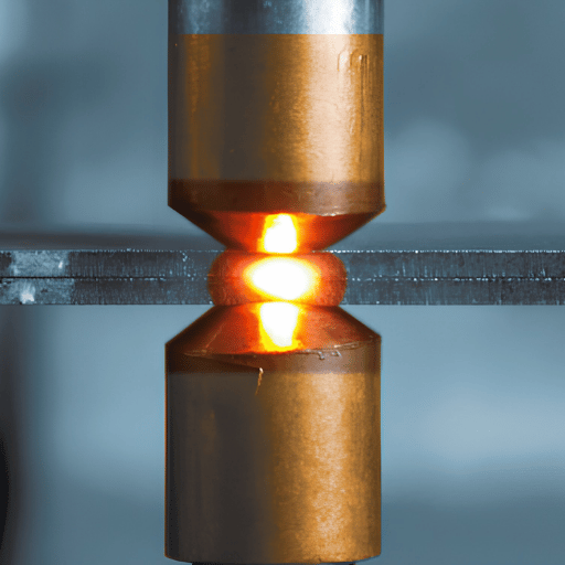
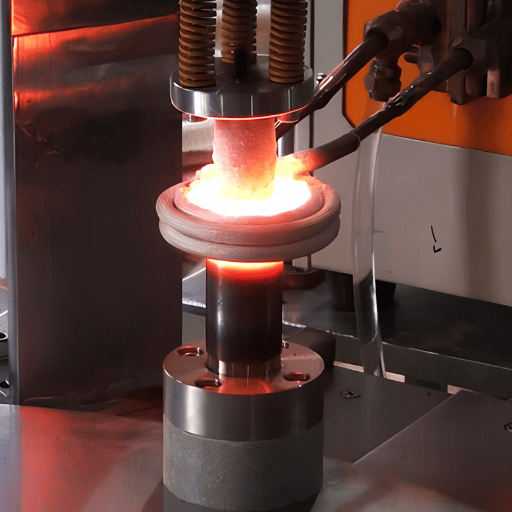
Resistance welding is a solid-state and fusion welding process that uses electrical resistance and clamping force to join metal workpieces. Electrodes carry a high-amperage, low-voltage current through the parts. At the interface between the two metal sheets — called the faying surface — electrical resistance is highest, so heat generation concentrates there. Metal at the faying surface reaches melting point and fuses under electrode forging pressure, forming a weld nugget without any filler metal or shielding gas.
TWI Global, one of the world’s leading welding research institutes, defines the process: “Resistance welding processes are used for joining sheet materials and consist of spot, seam, projection, and upset butt welding.” The defining feature is that no consumable electrode, filler wire, or flu× is required — the base metals themselves form the joint.
⚡ Resistance Welding — Quick Specs
Welding Current
1 kA – 100 kA
Electrode Force
1 kN – 1²0 kN
Weld Time
8 ms – 1,000 ms
Material Thickness
0.1 mm – 6 mm (spot)
Filler Metal
None required
Shielding Gas
None required
⚙ Engineering Note — Joule’s Law
Q = I² × R × t
Q=I ² Rt where Q = heat energy generated (joules), I = welding current (amperes), R = electrical resistance at the faying surface (ohms), and t = welding time (seconds). Because current is squared, doubling it quadruples the heat – making welding current the most powerful variable to control.
How the Resistance Welding Process Works: 4 Stages
- Squeeze: Electrodes squeeze the two workpieces under controlled force. Contact resistance at the faying surface is established.
- Weld (current on): Current flows. Joule heating causes the faying surface to reach melting point. A weld nugget begins to form.
- Hold (current off): Current stops. Electrode force is maintained to let the nugget solidify under pressure, which prevents cracks from shrinking.
- Release: Electrodes move away. Joint formation is complete — no weld finishing, grinding, or other cleanup required.
Source: NASA PRC-0009 resistance spot welding spec; TWI Global process overview.
5 Types of Resistance Welding — and When to Use Each
Electric resistance welding is not a single process — it is a family. AWS classifies four primary types, with flash welding often listed separately as a fifth. Each variant uses the same Joule heating principle but differs in electrode geometry, joint configuration, and the shape of the resulting bond.
❓ People Also Ask
What are the four basic types of resistance welds?
The four process types that the American Welding Society (AWS C1.1) recognizes are: (1) resistance spot welding – two points pressing on overlapping sheets; (2) resistance seam welding – wheel electrodes roll a sealed joint continuously; (3) projection welding – current focuses on embossed projections or fasteners; and (4) butt welding – end to end welding of rods, tube, or rails. Flash welding, which begins as an arc before pressure pushes the joint together, counts as a fifth type of process type.
1. Resistance Spot Welding (RSW)
Resistance spot welding uses a pair of copper alloy electrodes to clamp two or more overlapping metal sheets and pass current through a small contact area. A circular weld nugget — typically 3–12 mm in diameter — is the result. Spot welding is the highest-volume precision joining process in manufacturing, with automotive body assembly relying on it at scale.
Best for: Auto body panels, appliance sheet metal, electrical enclosures, brackets.
Electrode type: Truncated cone or dome-nose copper alloy tips.
Standard: AWS C1.1:2019 — Specification for Resistance Welding of Bare and Coated Low-Carbon Steel.
2. Resistance Seam Welding (RSEW)
Seam welding replaces point-contact electrodes with rotating copper wheel electrodes. As the workpiece feeds through, overlapping spot welds merge into a continuous, leak-proof seam. Mash seam welding uses narrower wheels that simultaneously weld and reduce the lap joint to near-parent-metal thickness.
Best for: Fuel tanks, radiators, HVAC ducting, aerosol cans, electrical transformer cores — any application requiring a hermetic (gas-tight or liquid-tight) seam.
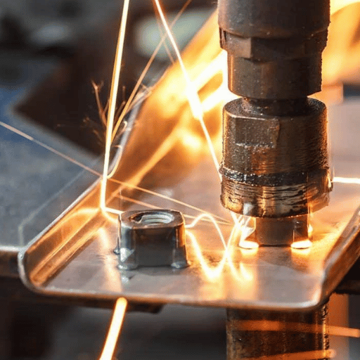
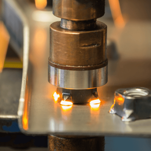
3. Projection Welding (PW)
Projection welding focuses contact resistance at pre-formed embossments (raised bumps) on one workpiece, or at the integral projections of a weld nut or stud. As current flows, the projection collapses and fuses to the mating surface. Multiple projections weld simultaneously, making this process e×ceptionally efficient for high-volume fastener attachment.
Best for: Weld nuts, studs, and bolt attachment to sheet metal; wire mesh production; cross-wire grids.
Advantage: Flat-face electrodes have long life because contact area is not concentrated on the electrode tip.
4. Resistance Butt Welding (RBW)
Resistance butt welding — also called upset butt welding — joins two metal pieces end-to-end. Both parts are clamped in copper jaw electrodes, brought into contact, and a current applied. Interface resistance creates heat; forging pressure upsets (squeezes) the hot metal together. No arc is involved. Common for welding wire, rod, chain links, and tubing ends.
5. Flash Welding (FW)
Flash welding is an end-to-end process where the parts are first brought into light contact under voltage, generating a series of small arcs (“flash”) that rapidly heat the joint faces to forging temperature. Parts are then forced together (upset) and current is cut. The key difference from butt welding: the arc-flash phase e×pels o×ides and contaminants before the forge, producing an exceptionally clean bond. Used for railway rail joining, saw blade manufacturing, and automotive wheel rims.
Which Resistance Welding Type Is Right for Your Application?
| Process | Joint Type | Key Feature | Typical Application |
|---|---|---|---|
| Spot (RSW) | Lap | High-speed point join | Auto body, appliances |
| Seam (RSEW) | Lap (continuous) | Hermetic sealed joint | Fuel tanks, radiators |
| Projection (PW) | Lap (fastener) | Multi-point simultaneous | Weld nuts, wire mesh |
| Butt (RBW) | Butt (end-to-end) | No filler, full cross-section | Wire, rod, chain |
| Flash (FW) | Butt (arc-assisted) | Self-cleaning arc flash | Rail, wheel rims, saw blades |
The Q=I²Rt Decision Model: 4 Parameters That Control Weld Quality
Every resistance welding difficulty can be explained as one or a combination of the four parameters: current (I), resistance (R), time (t), and welding force (F). Because Joule’s Law constrains heat generation to Q=IRt, and electrode force affects the contact resistance and weld solidification pressure, the four levers of the Decision Model interact. We refer to this framework as the Q=IRt Decision Model for Resistance Welding: a systematic approach to determine which one to change when the outcome isn’t right.
| Parameter | Role in Q=I²Rt | Typical Range (mild steel, 1.5 mm) | If Too Low | If Too High |
|---|---|---|---|---|
| Welding Current (I) | Dominant (squared) | 8–12 kA | Cold weld / no nugget | Expulsion / spatter |
| Welding Time (t) | Linear heat input | 10–20 cycles (60 Hz) | Undersized nugget | Electrode sticking / burn-through |
| Contact Resistance (R) | Heat concentration | Controlled via surface prep | Heat migrates to electrodes | Arc formation / surface damage |
| Electrode Force (F) | Sets R; controls solidification | 2–5 kN | High R → spatter; poor nugget | Too-low R → cold weld |
SWANTEC’s eight parameter resistance welding model builds not only on the four main variables but also on factors like electrode shape, surface condition, workpiece thickness, coating, and shunting effect of neighboring welds. In practice, adjusting the settings at setup and tooling determines all but two.
⚙ Pro Tip — MFDC Inverter Technology
MFDC (Mid-Frequency Direct Current) inverter welders are growing in adoption, particularly for advanced high-strength steels (AHSS) in automotive applications. Unlike single-phase AC welding machines — which remain the most widely used type in industry today — MFDC controllers deliver DC current at 500–4,000 Hz. Higher switching frequency enables faster feedback control, more precise current waveforms, and manufacturers report up to 35% energy reduction versus AC equivalents. If you’re processing AHSS or dual-phase steels, MFDC precision is worth the capital premium over conventional AC.
Material Compatibility: What Can (and Can’t) Be Resistance Welded?
Two physical properties govern a metal’s suitability for resistance welding: electrical resistivity and thermal conductivity. Resistance welding requires moderate resistivity (high enough to produce ample Joule heat at the faying surface but low enough to pass current freely without arcing) and moderate thermal conductivity (it is undesirable for a significant heat flux to flow into electrodes). Mild steel strikes an ideal balance and is easy to resistance weld; aluminum and copper are located at the most difficult ends of the spectrum.
| Metal | Electrical Resistivity (µΩ·cm) | Thermal Conductivity (W/m·K) | Weldability Rating | Key Challenge |
|---|---|---|---|---|
| Mild Steel (low-C) | 12–16 | 45–60 | Excellent ✅ | None — gold standard |
| Stainless Steel (304) | 70–78 | 15–17 | Good ⚠ | Work hardening; lower current needed |
| Aluminum (6061) | 3.7–4.0 | 155–160 | Difficult ⚠ | Oxide layer + high conductivity |
| Copper (pure) | 1.7 | 385–400 | Very Difficult ❌ | Conductivity too high; heat won’t focus |
| Zinc-coated Steel (GI) | 14–17 (steel base) | 45–55 | Good ✅ | Zinc vapour → electrode pickup |
⚙ Engineering Note — Spot Welding Aluminum
Aluminum’s electrical conductivity (roughly 9 times higher than that of mild steel) and thermal conductivity (roughly 3 times higher than mild steel) is high enough such that heat flux into the surrounding metal occurs faster than melting the faying surface. Aluminum’s naturally occurring oxide layer (A12O3) offers high resistivity and must be burned through by mechanical means prior to weldline formation. The best way to weld aluminum sheet electrically is therefore to apply 2-3 times the current density for 2-3 times as long (it takes roughly 2-3 times as long to burn through the oxide layer) as is used for steel, with increased electrode force to prevent expulsion and the additional tendency for the electrode faces to become fused to the workpiece. Aluminum sheet workpieces wear electrodes faster and require electrode dressing considerably more often in high-volume manufacturing. Resistance spot welding aluminum in a high-volume automotive application normally involves MFDC and forced electrode dressing.
⚠ Warning — Resistance Welding Copper
Copper’s exceptionally high thermal conductivity (385 W/mK) means that whatever Joule heat is produced in the work material at the faying surface is lost to the surrounding resistance welding heat sink faster than the workpiece reaches fusion temperature. These characteristics must mean a resistance weld structure with high aspect ratio openings for cooling cannot be practically produced using traditional RF power supplies. Normally wire is resistance welded to copper or copper-to-copper joints are assembled by resistance brazing, or laser or ultrasonic welding instead.
Resistance Welding vs. Arc Welding: Which Process Wins?
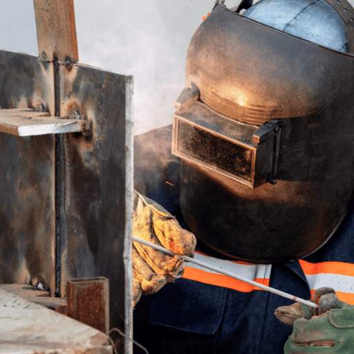
Resistance and arc welding are not competitors, although their technological boundaries do have some overlap. Some workpieces are best joined using the resistance process while others are best joined using an arc process. Choosing resistance welding over an arc process comes down to sheet thickness, production rate, joint access, batch size, and post-weld finishing requirements. Arc welding variants — including MIG, TIG, and submerged arc welding — suit different production contexts than resistance methods, and industrial welding applications frequently use both technologies on the same production line.
Is Resistance Welding Better Than MIG Welding?
Yes. For thermoplastic gauge 18 sheet metal, mass production, lap-joints, resistant spot welding is the most expedient solution. Its weld cycle time is less than 1 second with no filler wire, no shielding gas dependency, and no post-weld cleanup. MIG welding its equivalent joint over 5 times as long, requires consumables, and leaves a rough surface profile that often needs to be ground flat if it is to be painted or coated. For structural members, thick gauges, and single-structure production, MIG/TIG processes are more productive.
| Factor | Resistance Welding | MIG/TIG Arc Welding | Laser Welding |
|---|---|---|---|
| Speed (thin sheet) | ⭐⭐⭐⭐⭐ (fastest) | ⭐⭐⭐ | ⭐⭐⭐⭐ |
| Filler Metal Required | ❌ None | ✅ Yes (MIG) / Optional (TIG) | ❌ None |
| Shielding Gas | ❌ None | ✅ Yes | Optional |
| Joint Access Requirement | Both sides | One side | One side |
| Material Thickness Range | 0.1–6 mm (spot) | 0.5 mm – unlimited | 0.05–25 mm |
| Post-Weld Finishing | None required | Often grinding/cleanup | Minimal |
| Best For | High-volume sheet metal | Structural, thick-section | Precision, thin, dissimilar |
Industrial Applications of Resistance Welding by Sector
While arc welding rivals resistance welding in terms of sheet thickness, it flows short of its high-volume production capacity. The automotive industry consumes more resistance spot welds per annum than all other sectors combined, with enough component parts to number the equivalent of dozens of trillions of resistance spot welds per annum. There are currently far more resistance welding equipment installations than arc weldor installations worldwide.
📊 Resistance Welding — Scale by the Numbers
2,000–5,000
Spot welds per vehicle body (AWS research)
90M+
Vehicles/year using RSW in body assembly
~300 ms
Typical spot weld cycle time (steel, 1.5 mm)
$0
Filler metal or shielding gas cost per weld
Resistance Welding Applications by Industry
🚗 Automotive
All other joining equipment. Automobiles bodies in white, door shells and panels, seat frames and engine bay structures are all resistance spot or seam welded using fully programmable automation systems. AWS D1.1 and OEM-specific standards are the accepted benchmark for process control.
✈ Aerospace
All other joining equipment. Fuel cell brackets and other internal components are resistance spot welded using AWS D17.2-compliant process controls.
⚡ Electronics
Battery tab welding (capacitor discharge), terminals, PCB component leads. Ultra-short pulse times reduce energy input and heat damage to heat-sensitive components.
🏗 Construction
Structural steel wire mesh, rebar grids, metal cladding panels, HVAC ducting joints.
🔧 White Goods
Washing machine drums, refrigerator liners, dryer cabinets- high-volume thin sheet, perfect for automated spot welding.
🛢 Energy
Fuel tanks (seam welding), EV battery enclosures, solar panel frames. Fast-growing industry segment due to EV adoption.
📋 Application Scenario
An automotive Tier-1 supplier producing 180,000 car door panels annually runs 14 spot welds per door- that adds up to 2.52 million welds per year. Using a six-gun robot welding cell firing at 280 ms per cycle time, it completes its 14 weld sequence in under 4 seconds. Resistance spot welding with automation at this level is by far the most economical joining process.
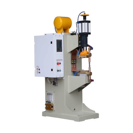
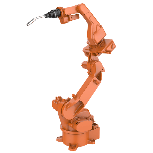
Automating Resistance Welding: Robotic Systems vs. Manual Machines
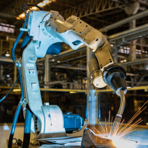
Pedestal spot welders and manual seam welders have serviced resistance welding shops for decades, but with increasingly strict materials, shorter cycles, and dwindling skilled labor skill pool, the business case for robotic spot welding has shifted drastically. Today’s question isn’t if to automate, but what level of demand warrants the capital investment. The International Federation of Robotics (IFR) consistently ranks the automotive sector as the world’s highest-density industrial robot user — with resistance spot welding robots representing one of the most widely deployed applications in body-in-white production.
📋 Real-World Upgrade Scenario
A sheet metal fabricator using two pedestal spot welders with three operators on shift-shift basis, producing 350 enclosures each day, had an average production rate of 3.8 welds/minute/operator and a rework rate of over 4% because of uneven electrode pressure. After installing a single robot welding station, welds per part at the same operator-machine combination dropped to 1.8/minute-and cycle time from 4.1 minutes to 1.8 minutes-and rework rate decreased to under 1%. Now one operator in a single robot cell oversees a two-shift operation, freeing two manual welders to other work. Roi was achieved in less than 14 months.
Manual Spot Welding vs. Robotic Cell — Performance Comparison
| Metric | Manual Pedestal Welder | Robotic Welding Cell |
|---|---|---|
| Weld Rate | 3–5 welds/min | 10–15 welds/min |
| Arc-On / Active Time | 25–35% | 85–95% |
| Positional Repeatability | ±1–3 mm (operator dependent) | ±0.025–0.1 mm |
| Weld Defect Rate | 3–8% (varies by operator) | <1% |
| Shift Coverage | 1–2 shifts (fatigue limit) | 3 shifts / lights-out |
| Typical ROI Payback | — | 12–24 months |
Data: robotic welding performance benchmarks from industry automation specialists; SML ISUZU robotic RSW case study (Journal of Advanced Manufacturing Processes, 2021).
When Does Robotic Spot Welding Automation Make Financial Sense?
- Production volume >200 assemblies/day: representative small-to-medium production volume for ROI calculations resulting in break-even capital payback in 24 months with two-shift operation.
- Joint consistency: automated welding cells require very repeatable part positioning, run fixtures or vision systems.
- Rework critical welds: don’t underestimate the impact of improving welding cell integrity when your current rework rate exceeds 2-3%.
- Labor crunch: a single welding robot replaces the need for 2-3 skilled welders/operators per shift.
- Lights-out operation: robots operate three shifts a week-ends.
Ideal starting point for fabricator fielding multiple robots to compare spot welding robot cost breakdown for different cell applications or structure: single robot welding cell- a ferreted in, ready-to-run design consolidates 6 axis robot, servo-powered spot welding gun, positioner, and safety enclosure in the shortest possible lead time. Larger custom cells take longer and may not deliver a faster ROI for small-to-mid volume applications.
Zhouxiang Welding Automation
Ready to Automate Your Resistance Spot Welding?
Configuration Zhouxiang single robot robotic spot welding cell- built for small-to-mid volume fabricator seeking faster cycle times, less rework, break-even ROI within 12-24 months.
Common Resistance Welding Defects and How to Prevent Them
⚠ Quality Alert
Welding engineers consistently rank electrode wear as the number one root cause of recurrent resistance welding quality issues – out-of-spec nugget diameter readings being the most prominent example. electrode condition should be modeled as a first-order process variable, not a maintenance after-thought.
Electrode Wear Causes & Prevention: Resistance welding process anomalies tend to follow predictable patters – each defect type is associated with a certain known root-cause of the Q=IRt equation.
Once you identify the deformity mode, diagnosis and solution become a systematic exercise. This checklist contains the top five failure modes to preempt and their associated counter-measures according to electrode manufacturer recommendations, resistance spot inspection standards and engineer troubleshooting guidance. See our weld inspection standards guide and our weld testing and quality inspection deep-dive for in-depth analysis.
1. Expulsion (Weld Spatter)
Cause: Too high current density, too little electrode force, degraded electrode geometry. Cause: Molten metal ejects from the weld zone.
2. Cold Weld (Undersized Nugget)
Prevention: Drop the current or increase the force; re-establish the original gear profile: check work place contamination on work pieces.
3. Electrode Degradation (Mushrooming)
Cause: Not enough heat current too low, weld time too short, contact resistance thus too low due to the presence of worn electrodes with large face diameter. Prevention: Check parameter setting against weld schedule. Increase the current or weld time.
Dress electrodes to the target face diameter.
4. Surface Contamination / Oxide Layer
Cause: Repeated thermal cycling conforms the electrode tip face shape – face diameter increasing (“mushrooming”) thus further decreasing the current density.
This is the most common root-cause for gradual weld quality drifting. Prevention: Implement an auto-electrode dressing schedule (generally once every 50-200 welds depending on material and coating). Track weld count per electrode set.
5. Shunting Effect
Cause: Contact resistance is uncontrollably increased at the faying surface or the electrode tip due to oil, scale, high oxide content or zinc droplets contaminating the face or work piece surfaces. Result: Nugget formation becomes length- and difficult to control.
Prevention: Clean raw metal sheets with solvent before you send them through the weld cell. Expect zinc pickup on electrodes when welding galvanize, and schedule electrode cleaning accordingly. Oxide removal is essential on aluminum surfaces.
⚙ Engineering Note — Electrode Dressing Protocol
If you place a new spot weld in a hole that is too close to an existing weld, current shunts through the solidified w-449g27f- nugget instead of focusing at the faying surface, reducing the heat delivered to the weld and increasing defect rate. The minimum pitch between spot welds ranges by the effective nugget diameter as outlined by American Welding Society C1.1 welding standards: the typical minimum is 3-5 the nugget diameter.
General electrode tips and tricks: the tip dresser, in combination with a well-programmed situation, is the best tool for minimizing the life of your electrode. A tip dresser is a small, automated cutter that removes a thin layer of copper alloy to restore the contact face diameter and geometry. Over-dressing shortens life, under-dressing allows the electrode to mushroom.
Automate your electrode tip dresser cycles in relation to your apply-sets-with-through-and-through welding situation and the manufacturer suggested electrode life. Keep a log of tip life over the course of the application. 2Different heat paths of the gun arms cause the left and right gun electrode tip life cycles to be different!
Resistance Welding in 2025–2026: Market Trends and Technology Evolution
The situation looks to be more of a steady, sustained growth path of the resistance welding equipment market driven mainly by increased EV production, the adoption of newer high strength steels and the steady evolution from manual to automated welding systems. The right resistance welding machine to choose today is the one that aligns with the presence of materials and process technology trends for the next five years.
📈 Resistance Welding Market — 2026–2035 Outlook
3.8%
Market CAGR (2026–2035)
$1.22B
Market size 2026 (est.)
$1.71B
Projected market size 2035
Source: BusinessResearchInsights, Resistance Welding Machinery Market Report.
Key Technology Trends Shaping Resistance Welding Through 2026
⚡
MFDC Adoption in AHSS Processing (2024–2026)
Mid-Frequency DC inverter technology is gaining new automotive applications, especially for advanced high-strength steel (AHSS) grades where good current control is a must. Academic research in 2024 confirms the steady rise of Mid Frequency DC (MFDC) technology in automotive body-in-white applications, although the most common machine type is still single phase AC. New greenfield automotive body shop projects tend to specify MFDC equipment.
🚗
EV Battery Housings and UHSS Drive New Demand
Electric vehicle platforms make use of greater shares of ultra-high strength steel (UHSS) than traditional internal combustion engine vehicles – along with more aluminum in battery packaging – thus creating a need for both higher performance resistance welding equipment capable of welding 1,500 MPa class steels as well as specialized low-resistance aluminum welding systems with shorter pulse times.
🤖
Industry 4.0: Adaptive Control and IoT Integration
Modern resistance welding controllers offer feedforward adaptive current control – wirelessly controlling a weld schedule based on real-time monitoring of the dynamic resistance curves from the actual weld. Combined with Internet of Things (IoT) monitored weld count, electrode burn-back and explosion, electrode dressing activity, the software-enabled integration with predictive maintenance schedules ultimately eliminates the fixed-target electrode dressing schedules that squander valuable electrode life. The traditional spot welding robot vis arc welding debate is going toward robotic resistance welding in these smart factory settings.
🔋
Capacitor Discharge Welding for Miniaturized Electronics
The boom in the capacitor discharge (CD) resistance welding market is being driven by the electronics and battery manufacturing boom, since it forms microsecond impulses for welding thin foils, thermocouple wires or battery cell tabs in a way that 50/60 Hz AC timing cannot.
Frequently Asked Questions — Resistance Welding
Conclusion
Resistance welding’s strength is its combination of speed, cleanliness, and consistency at high production volumes. Spot welds on body panels, sealed seams on fuel tanks, projection weld nuts on structural brackets — the underlying Q=I²Rt relationship governs every joint in each of these scenarios. Get the four parameters right — current, time, contact resistance, and electrode force — and the process is extraordinarily reliable.
The resistance welding cell market is maturing: MFDC technology, primarily in aerospace and automotive early adoption, is expanding into industrial sectors; robotic welding automation systems are citing return on investment in the 200+ assemblies/day shop; Industry 4.0 adaptive control is replacing fixed parameter time tables with real-time, live weld schedules. For manufacturers balancing between manual resistance welding and automation, the facts on cycle time, consistency, and production economics consistently support robotic automation – especially in a high-repeat lap-joint sheet metal environment where the spot welding robot’s consistency impacts reject rate reduction.
To judge how a robotic resistance welding work cell would serve your production needs, view Zhouxiang’s 1-robot welding station – a ready-made lap-joint assembly automation solution sized for small-to-medium volume fabricators.
References & Sources
- TWI Global — Resistance Welding Overview (The Welding Institute, UK)
- American Welding Society — AWS C1.1:2019, AWS D17.2 (Resistance Welding Standards)
- Wikipedia — Electric Resistance Welding (process overview, current ranges)
- NASA Technical Standard PRC-0009 — Resistance Spot Welding (nugget diameter specification)
- Journal of Advanced Manufacturing Processes (2021) — SML ISUZU robotic RSW cycle time optimization
- ResearchGate (2024) — Comparative study of AC and MFDC resistance spot welding for AHSS grades
- BusinessResearchInsights — Resistance Welding Machinery Market Report (CAGR 3.8%, 2026–2035)
Related Articles
Spot Welding Robot versus Arc Welding: What’s Suitable for Your Facility?
Robotic Welding Technology: What Every Fabricator Should Know
Welding Robot Cost Breakdown: What to Budget in 2025
Industrial Welding Applications: Processes and Sector Guide
Robotic vs Manual Welding: ROI Analysis for Small Fabricators
Editorial Note: This guide was developed by the Zhouxiang technical content team, drawing on published welding standards (AWS, NASA), industry research databases, and manufacturer process data. Where third-party data points are cited, sources are referenced. Industry-practice claims without primary literature support are qualified with language such as “welding engineers report” or “industry practitioners indicate.” Market data sourced from third-party research reports is cited with the originating organization; Zhouxiang does not independently verify market size projections. For welding process decisions involving safety-critical applications, consult a certified welding engineer (CWE) or your equipment manufacturer’s application team.