Get in Touch with Zhouxiang

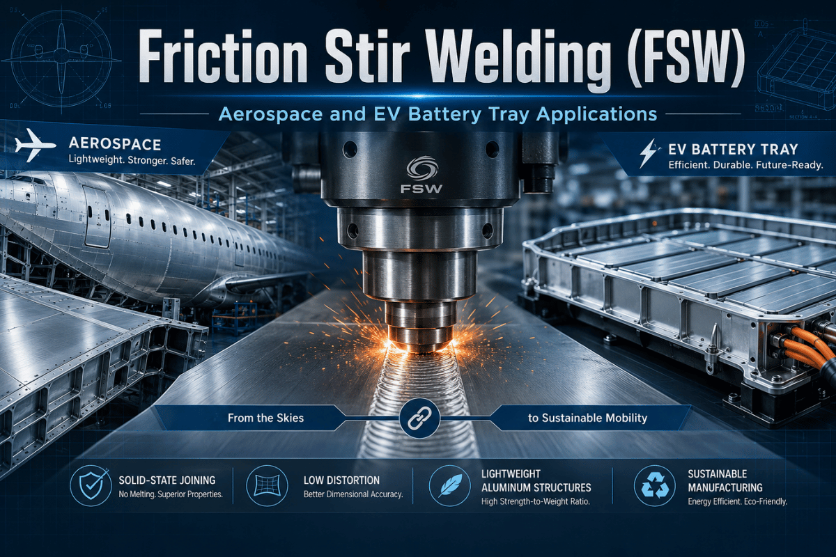
Friction Stir Welding (FSW): Aerospace and EV Battery Tray Applications
Contents
show
Friction stir welding (FSW) solves the problem arc welding cannot: joining high-strength aluminum alloys that crack when they cool from a liquid melt. Since Wayne Thomas invented the process at TWI in 1991, FSW has expanded from aerospace R&D into automotive production lines, EV battery manufacturing, and large-scale shipbuilding. A September 2025 breakthrough from Pacific Northwest National Laboratory has now cleared the last barrier to flexible assembly-line robotic FSW deployment.
Quick Specs: Friction Stir Welding (FSW)
| Process type | Solid-state joining — base material never melts |
| Operating temperature | 80–90% of base material melting point |
| Invented | 1991, TWI Ltd, Cambridge UK (Wayne Thomas) |
| Primary material | Aluminium alloys — all grades 1xxx through 7xxx |
| Also welds | Steel, titanium, copper, nickel, dissimilar metals |
| Thickness range (Al) | 0.3 mm – 75 mm, single pass |
| Key standards | AWS D17.3/D17.3M:2021 (aerospace) · ISO 25239 (general) |
| 4 control parameters | Downforce · rotational speed · travel speed · tilt angle |
| Consumables (Al) | None — no filler wire, shielding gas, or flux |
| Exit hole | Yes — design accommodation required at weld termination |
What Is Friction Stir Welding?
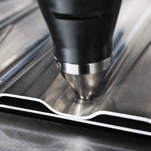
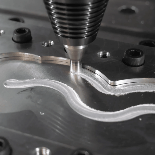
Friction stir welding is a solid state welding process — the base material never reaches its melting point. A non-consumable tool consisting of a shoulder and a probe pin rotates at high speed and plunges into the joint between two workpieces. Frictional heat raises material temperature to 80–90% of its melting point, causing the metal to plasticize without liquefying. The rotating tool then traverses along the joint line, mechanically stirring the softened material and forging a solid state joining bond behind it.
Three zones define the weld cross-section. The weld nugget directly beneath the tool shoulder undergoes dynamic recrystallization, producing fine equiaxed grains with superior mechanical properties compared to cast fusion weld metal. The thermomechanically affected zone (TMAZ) surrounds the nugget — mechanically deformed but not recrystallized. The outer heat affected zone (HAZ) is thermally altered without mechanical deformation, similar to arc welding HAZ but considerably narrower.
Wayne Thomas at TWI Ltd in Cambridge, UK invented FSW in 1991. TWI describes it as achieving “one of the shortest times from invention to widespread industrial use” — commercial aerospace production adopted FSW within four years of its patent filing. The absence of the liquid phase is the process’s defining metallurgical advantage: since material never melts, solidification defects (porosity, hot cracking, solidification segregation, slag inclusions) cannot physically form. This is why FSW is the enabling joining technology for the 2xxx series and 7xxx series of aluminum — the high-strength alloys classified as “non-weldable by conventional arc processes” due to their susceptibility to solidification cracking.
See also: Industrial welding process overview
How the FSW Process Works: The 4 Key Parameters
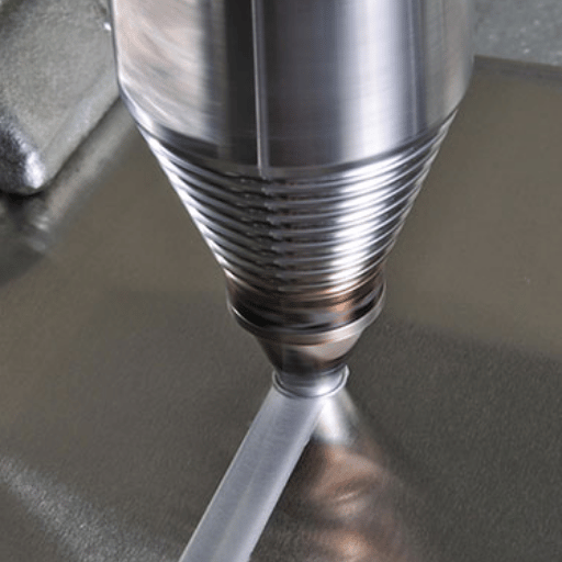
Each FSW pass runs in three sequential phases: plunge (the rotating tool descends until the shoulder contacts the workpiece surface), dwell (brief rotation builds thermal equilibrium at the joint), and traverse (the tool moves along the joint at controlled travel speed while maintaining downforce). The weld consolidates directly behind the advancing shoulder.
Four variables control every FSW outcome:
-
- Downforce (kN): The vertical force pressing the shoulder into the material. This is the most critical and most underestimated parameter — insufficient downforce produces a wormhole tunnel defect; excess downforce causes flash and workpiece thinning.
- Rotational speed (RPM): Controls heat input. Higher RPM raises material temperature. For 6061-T6 aluminum at 5mm thickness, typical starting ranges are 400–1,000 RPM.
- Travel speed (mm/min): Controls heat distribution per unit of weld length. A peer-reviewed comparative study on AA5083-H111 aluminum found maximum ultimate tensile strength at 400 mm/min travel speed — the balance point between over-annealing (too slow) and tunnel defect formation (too fast).
- Tilt angle (degrees): The tool tilts 1–3° toward the direction of travel, directing plasticized material downward and backward into the weld path to ensure complete consolidation.
Engineering Note – Typical FSW Parameter Ranges by Material
| Parameter | Al 5mm (6061-T6) | Al 20mm | Steel (PCBN tool) |
|---|---|---|---|
| Rotational Speed | 400–1,000 RPM | 200–500 RPM | 200–500 RPM |
| Travel Speed | 100–400 mm/min | 50–150 mm/min | 50–200 mm/min |
| Downforce | 5–15 kN | 20–40 kN | 30–80 kN |
| Tilt Angle | 1–3° | 1–3° | 1–2° |
Ranges from published literature. Qualify against specific material batch, tool geometry, and machine configuration before production qualification.
⚠ Common Mistake — Downforce Underestimation
A fabrication engineer setting up FSW for 6061-T6 panels for an EV battery tray typically has no reference frame for the 5,000+ lb (22+ kN) vertical load FSW applies to 5 mm aluminum sheet. Engineers arriving from arc welding backgrounds configure fixtures for arc-compatible clamp loads — far below what FSW demands. The result: workpiece movement mid-weld, out-of-specification parameter excursion, and a weld that fails radiographic inspection. Fixture engineering should be your first FSW design decision, not an afterthought.
What Materials Can Be Friction Stir Welded?
The material range FSW can join is wider than most engineers expect when they first encounter the process through aluminum applications. Aluminium alloys across all commercial grades are the primary application, but the process handles a broader portfolio — including materials that fusion welding handles poorly or not at all.
| Material | Grade / Type | Weldability | Key Notes |
|---|---|---|---|
| Aluminium (structural) | 1xxx, 3xxx, 5xxx, 6xxx | Excellent | No filler, no gas; superior joint quality vs. arc |
| Aluminium (aerospace) | 2xxx series, 7xxx series | Excellent | Non-weldable by fusion — FSW is the only viable process |
| Steel | Mild, HSLA, pipeline X65/X80/X100, AHSS | Good (<8mm) | Requires PCBN or MP159 tooling; tool wear increases rapidly above 12mm |
| Titanium | Grade 1–4, Ti-6Al-4V | Good | PCBN tooling required; aerospace structural applications |
| Copper | Commercially pure, Cu alloys | Good | Heat sinks, electrical conductors, battery terminals |
| Nickel alloys | Grades 200, 600, 625, 718 | Moderate | Validated for specialized applications (MegaStir) |
| Dissimilar metals | Al-to-Cu, Al-to-Steel | Achievable | Avoids brittle intermetallics formed in fusion welding; joint design critical |
| Metal matrix composites | Al-MMC, SiC-reinforced | Achievable | Solid-state process preserves reinforcement distribution |
Can Friction Stir Welding Be Used on Steel?
Yes. FSW welds carbon steel, HSLA pipeline grades (X65, X80, X100), automotive AHSS, and austenitic stainless steel when the correct tooling is selected. Tool material determines feasibility: aluminum FSW uses H13 tool steel at relatively low cost; steel FSW requires PCBN tooling (polycrystalline cubic boron nitride) or MP159 cobalt-nickel superalloy, at $2,000–$5,000 per tip set.
TWI notes that FSW of steel sections exceeding 12mm in thickness and welds spanning several meters presents ongoing tool wear and failure challenges. For steel under 8mm — automotive door panels, structural members, thin-wall pipeline joints — FSW is industrially deployed and commercially proven.
The assumption that FSW is aluminum-only is the most persistent misconception in the process selection decision. Dissimilar materials joints — Al-to-Cu for battery terminals, Al-to-steel structural connections, and titanium aerospace brackets — are FSW application areas where fusion welding produces unacceptable results — brittle intermetallics, porosity, or alloy volatilization — and FSW is the practical alternative.
FSW vs. Arc Welding: Advantages, Limitations & When to Choose
The justifications for the quantum leap of FSW over arc welding stand fully on the metallurgical benefits: the solid-state system is immune to all of the solidification flaws that underwrite the quality costs in MIG, TIG, and SAW welds – not through narrower controls, but through process physics.
A 2023 peer-reviewed comparative study of AA5083-H111 aluminum at 5mm plate thickness found: FSW joints achieved 46–50% hardness improvement above the base material — versus 31–35% for TIG joints and 24–29% for MIG joints. Radiographic inspection showed zero internal defects in FSW specimens; TIG and MIG specimens exhibited lack of fusion (LOF), lack of penetration (LOP), and porosity across multiple samples.
FSW advantages over arc welding:
- No filler wire, shielding gas, flux – direct consumable cost elimination
- HAZ considerably narrower than arc welding — less softening adjacent to the weld line
- 30-50% less weld distortion – less straightening needed after welding
- No UV radiation, minimal dust – improved worker safety
- Single pass capability up to 75mm on aluminum – no need for multi-pass welding procedures
- Zero porosity, hot cracking, solidification flaws – structural proof by mechanics
FSW limitations relative to arc welding:
- Exit hole at the end of weld – must provide run off tab or accommodate design
- Significantly higher capital equipment costs (~$110,000 USD) for FSW ($50,000-$200,000+ output) versus arc equipment ($2,000-$10,000+ output)
- Significantly higher clamping force requires – fixture design shockingly expensive
- Significantly constrained joint geometry due to accessibility limitations – big shop multi-position freeweld incapable
Process Selection Matrix — FSW vs. Arc Welding
| Your application profile | Recommended process |
|---|---|
| Aluminium + high production volume + distortion-critical + no filler requirement | FSW — strongest business case |
| 2xxx or 7xxx aluminum that “cannot be arc-welded” (solidification cracking) | FSW — only viable option |
| Complex 3D geometry + multi-position access + low production volume | Arc welding — FSW fixturing cost not justified |
| Dissimilar Al-to-steel, weight-critical structural joint | FSW with PCBN tooling |
| Steel + established arc welding WPS + low CAPEX budget | Evaluate full FSW TCO before switching |
Common error – Using arc shielding mismatch assumptions with FSW inaccessible access seams
Engineers who design FSW assemblies using distortion tolerances calibrated for MIG or TIG welding systematically over-engineer fixturing and finishing operations. FSW weld distortion runs 30–50% lower than arc welding on equivalent aluminum joint geometries. Carrying arc-calibrated tolerances into FSW programs adds unnecessary material, cost, and manufacturing time.
See also: submerged arc welding guide MIG robotic welding workstations
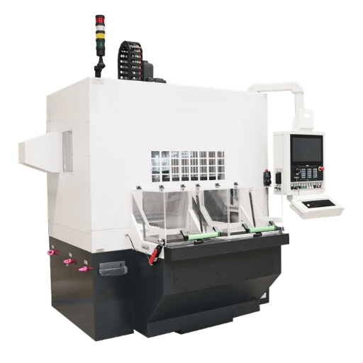
FSW Equipment and Tooling: Machine Types & Specifications
Four factors effect FSW machine choice: the dimension of work envelope needed, the downforce capacity demanded by the joint, whether forced controlled or position controlled operation is required for the material, and the production scale appropriate for capital equipment needs.
| Machine Type | Typical Application | Force Capacity | Best Fit |
|---|---|---|---|
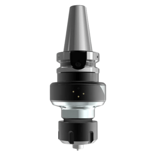
| CNC-integrated FSW head | Existing CNC machining centre upgrade | 10–30 kN | Low capital entry; flexible Al production |
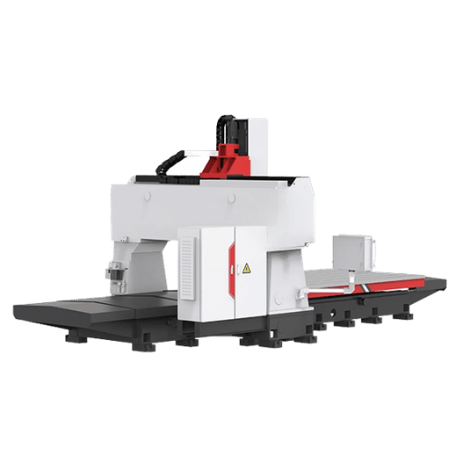
| Standalone gantry FSW | Batch production, flat and curved panels | 20–100 kN | Aerospace, rail, shipbuilding panels |
| Robotic FSW (6-axis) | Curved surfaces, assembly-line integration | 5–20 kN | Automotive, EV battery tray production |
| Dedicated production FSW | High-volume fixed production lines | 50–200 kN | Aerospace structural panels; large Al plate |
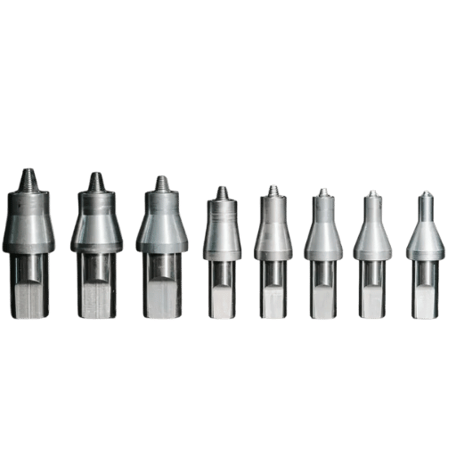
Tooling selection by material: H13 tool steel handles all aluminium alloy grades at low cost. A single H13 tool set welds 800–1,500 meters of aluminum joint before replacement — eliminating the per-meter filler wire cost entirely. PCBN (polycrystalline cubic boron nitride) is required for steel and titanium FSW; MP159 cobalt-nickel superalloy suits lower-temperature steel applications where PCBN’s brittleness is a structural concern. Tool shoulder diameter — available in 25mm, 38mm, and 50mm — scales with material thickness.
How Much Does a Friction Stir Welding Machine Cost?
FSW machine cost varies by type and specification. The lowest-capital entry point is a FSW head integrated into an existing CNC machining centre, at under €100,000 (~$110,000 USD). Standalone FSW systems begin at $50,000–$200,000 for basic setups; production-scale gantry FSW with force control and robotic integration ranges from $200,000 to over $1 million. Key cost drivers are working envelope size, spindle force capacity (5–100 kN), tool-change automation, and force-controlled vs. position-controlled operation.
Tooling: Additional cost (rough estimate) for an H13 tooling set for aluminium FSW projects: $500-$2,000; additional cost for steel or titanium FSW welding (PCBN tips): $$2,000 per set – $2,000 for a complete set of FSW equipment. Global market size for FSW equipment was $262MM in 2024 and will grow to $460MM in 2034 (CAGR ~ 6%) with really the only well-identified driver in the market being EV battery tray and aerospace structure applications.
Explore Zhouxiang’s Intelligent Welding Systems
Zhouxiang approach for gantry robotic platforms, designed for force-controlled applications, exploits the same basic configuration architecture adopted for integrated-scale FSW trials. Discuss your application needs with the Zhouxiang engineering team.
Where FSW Delivers Value: Industry Applications by Sector
| Industry | Application | Material | Key Benefit |
|---|---|---|---|
| Aerospace | Fuel tanks, fuselage panels | 2xxx, 7xxx Al | Only viable joining process for non-weldable alloys; SpaceX Falcon 9 propellant tanks |
| Automotive | Body-in-white, EV battery trays | 6xxx Al, AHSS | Weight reduction; eliminates post-weld heat treatment; zero filler consumable |
| Shipbuilding | Deck panels, hull structures | 5xxx Al (AA5083) | Zero internal defects vs. LOF/porosity in MIG/TIG; low distortion on long seams |
| Rail | Passenger carriage extrusions | 6xxx Al | Long-seam efficiency; minimal distortion on extruded profiles |
| EV Battery | Battery enclosure trays | 6061-T6 Al | Eliminates post-weld heat treatment; leak-free sealing; thermal management preserved |
| Electronics | Liquid cold plates, heat sinks | Al, Cu | Leak-free joints; no flux contamination; thermal conductivity preserved |
A structural fabricator bidding on EV battery enclosures for an automotive OEM in 2025 switched from MIG to FSW for 6xxx-series aluminum panel assembly. FSW eliminated the post-weld heat treatment cycle — a 4-day-per-batch process that existed solely to restore weld-zone properties degraded by fusion heat input. Because FSW never overheats the HAZ, aluminum temper is preserved in-process. The fabricator recovered 4 production days per batch without any additional capital investment in heat treatment capacity.
TWI describes FSW’s adoption trajectory as “one of the shortest times from invention to widespread industrial use.” SpaceX uses FSW for the main propellant tanks on the Falcon 9 rocket — a 2xxx-series aluminum application where fusion welding was not a feasible option.
See also: Aerospace welding applications Structural welding systems Shipbuilding welding robot solutions
FSW Weld Quality: Joint Strength, Defects & Inspection Standards
How Strong Is a Friction Stir Weld?
FSW joints in aluminium alloys achieve 80–95% of base metal ultimate tensile strength (UTS) without post-weld heat treatment — outperforming TIG and MIG by a wide margin on the same high-strength alloys, which typically reach 50–70% joint efficiency. For 7075-T6 and 6061-T6 dissimilar joints, untreated FSW joint efficiency reaches 67% (207 MPa); solution-aging post-treatment raises this to 94% (290 MPa). For steel FSW joints, mechanical properties replicate base material to within 5–10%.
“FSW’s solid-state microstructure — fine, dynamically recrystallized grains in the weld nugget — consistently outperforms the coarse cast structure of fusion weld metal, particularly in fatigue and fracture toughness. For high-strength aluminum alloys, this is not a marginal improvement. It is a fundamental metallurgical advantage that no amount of arc welding parameter optimization can replicate.”
— Glenn Grant, Materials Scientist, Pacific Northwest National Laboratory (PNNL)
Applicable inspection standards:
| Standard | Scope | Edition |
|---|---|---|
| AWS D17.3/D17.3M | Friction stir welding of aluminium alloys for aerospace applications | 2021 (3rd edition) |
| ISO 25239 | Friction stir welding — Aluminium (general industrial use) | 2020 |
Common FSW defects and their root causes:
- Tunnel defect (wormhole): The most common FSW defect. Root cause: insufficient heat input — travel speed too fast, RPM too low, or downforce too light. Material does not flow completely to fill the weld path. Not visible from the surface; detected by ultrasonic testing (UT) or radiography.
- Kissing bond: Insufficient tool penetration leaves a bond plane that passes visual inspection but opens under cyclic loading. The most dangerous FSW defect type — undetectable by visual inspection or standard RT. Phased array UT (PAUT) is the required NDT method for reliable detection.
- Flash: Excess material extruded at the weld surface. Root cause: excessive downforce or rotational speed. Identified visually. Usually not structurally significant, but indicates parameter excursion requiring correction.
See also: Weld testing methods · Weld inspection guide · Welding Procedure Specification (WPS)
FSW Cost Analysis: Investment, ROI & Decision Framework
The FSW business case is not a machine price comparison. It is a total cost of ownership (TCO) calculation across three cost centers: consumables eliminated, throughput gained, and quality costs avoided.
Direct operating savings — aluminium FSW vs. arc welding:
- Filler wire eliminated: $0.50–$2.00/meter of weld (material plus machine overhead)
- Shielding gas eliminated: $0.10–$0.30/meter
- Post-weld heat treatment cycle eliminated (6xxx/7xxx-series): $50–$500 per production batch
- Post-weld straightening reduced 30–50% — fixture and finishing labor savings
- Tool life: 800–1,500 meters per H13 tool set for aluminium — predictable, schedulable tooling cost
Decision Framework: Buy / Outsource FSW / Maintain Arc
| Pathway | Best fit | Decision trigger |
|---|---|---|
| Buy FSW machine | Annual Al weld >50,000m; dedicated product line | Consumables payback <18 months at current volume |
| Outsource FSW | <50,000m/year; mixed materials; irregular demand | Per-meter service cost < in-house TCO |
| Maintain arc welding | Complex 3D geometry; multi-position; established arc WPS | 3-year FSW savings < retooling cost |
Breakeven scenario: a fabrication shop running 200,000 meters of aluminum weld annually, at $15/meter combined filler and gas savings, recovers $3M annually from consumable elimination alone. Against a $400,000 FSW system investment, breakeven occurs at approximately 27,000 meters — under 6 months at full production volume, accounting for commissioning and parameter development time.
⚠ Hidden TCO Items Engineers Frequently Undercount
- PCBN tooling wear (steel FSW): $2,000–$5,000 per tip; wear rate must be modeled from material-specific test data, not assumed from aluminium benchmarks
- Fixture capital (conventional FSW): $50,000-$200,000 per joint configuration- reduced dramatically by recent self-fixturing robotic systems (see H2-9)
- Parameter qualification time: 20-80 hours per new joint geometry, including destructive coupon testing prior to production WPS approval
See also: Robotic welding ROI calculation Welding robot cost breakdown
Robotic FSW in 2025: The Automation Breakthrough
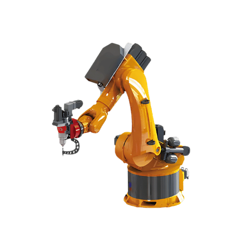
The primary barrier to assembly-line FSW deployment has always been fixturing. Traditional FSW machines exert up to 5,000 lb (22 kN) of vertical downforce — requiring purpose-built clamping fixtures for every joint configuration. Custom fixtures for a single joint geometry cost $50,000–$200,000, making FSW economical only for dedicated batch production on fixed product lines, not for the flexible joint-mix environment of automotive assembly.
On September 17, 2025, Pacific Northwest National Laboratory published the result that changes this calculation. PNNL engineers Mitch Blocher and Piyush Upadhyay, working under the U.S. Department of Energy’s Vehicle Technologies Office, demonstrated a self-fixturing robotic FSW system: the FSW rotating tool and a miniature backing plate mount on the same robotic arm in a closed force loop. The arm absorbs its own reaction load internally — no external fixture required. The self-fixturing problem is solved.
The production implications are direct:
- Flexible assembly lines can handle multiple joint types without a single fixture changeover cost
- Curved surfaces — roof rails, EV battery enclosure flanges, structural extrusions — are now accessible to robotic FSW without custom tooling
- Fixture cost for new joint types drops from $50,000–$200,000 to near-zero
- 4-arm robotic FSW setups become economically viable for high-volume body-in-white production
The automotive body-in-white application is concrete: four robotic FSW arms welding aluminium floor and structural sections in place of spot-welded steel assemblies delivers 40% weight reduction, eliminates all filler wire and shielding gas, and runs under fully automated force-feedback control. PNNL’s breakthrough makes this feasible on production-mixed lines where joint types change daily.
Beyond FSW itself, friction stir deposition (FSD) extends the process family into additive manufacturing: the same rotating tool deposits material for repair and near-net-shape component fabrication rather than joining two existing workpieces. Engineering teams already qualified in FSW parameter development can transfer that expertise to FSD system operation with relatively short learning curves.
The FSW equipment market, at $262 million in 2024, is projected to reach $460 million by 2034 at approximately 6% CAGR — driven primarily by EV battery manufacturing and aerospace structural integration. Search volume for “friction stir welding machine” rose 56% between May and October 2025 — a confirmed commercial signal that procurement activity is accelerating ahead of that market growth.
Zhouxiang’s intelligent welding systems provide the gantry and robotic configurations compatible with force-controlled FSW integration — the same force-feedback architecture that PNNL’s work confirms as the enabling technology for production-scale FSW. See: Robotic welding technology guide · Automated welding systems buyer’s guide
Frequently Asked Questions About Friction Stir Welding
How strong is a friction stir weld?
FSW joints in aluminium alloys achieve 80–95% of base metal UTS — well above what TIG or MIG achieves on the same high-strength alloys. For 2xxx and 7xxx series aluminum, FSW is frequently the only viable process: fusion welding produces solidification cracks in these alloys, making the strength comparison moot. Where arc welding cannot produce a sound joint at all, FSW joint efficiency is not the relevant metric — availability is.
Is friction stir welding expensive?
Machine capital cost is higher than arc welding equipment ($50,000–$200,000+ vs. $2,000–$10,000). However, FSW eliminates filler wire, shielding gas, and post-weld heat treatment for aluminium applications. At production volumes above 20,000–50,000 meters of aluminium weld per year, FSW commonly pays back within 6–24 months on consumables savings alone, before quality improvement and rework elimination are factored in.
Can FSW be used on steel?
Yes. FSW welds carbon steel, HSLA pipeline grades X65/X80/X100, and austenitic stainless steel using PCBN or MP159 tooling. Sections under 8mm are industrially proven. Tool wear climbs sharply above 12mm thickness, and PCBN tip cost ($2,000–$5,000 each) must be included in total cost of ownership calculations for any steel FSW business case.
What is the difference between friction welding and friction stir welding?
Conventional friction welding (inertia or continuous-drive) rotates one workpiece against the other while applying axial compressive force — no traversing tool, limited to cylindrical and axisymmetric joint geometries. FSW uses a traversing rotating tool that moves along any linear or curved joint line on sheet, plate, or extruded sections — handling butt joints, lap joints, T-joints, and corner joints that conventional friction welding cannot access.
Which industries use friction stir welding most?
The aerospace industry has made the greatest progress in terms of depth of application (e.g. fuel tanks and fuselage panels for non-weldable aluminum alloys, since the mid-1990s). The automotive industry is the fastest growing segment, specifically due to the efforts of EV battery tray and the body-in-white weight reduction programs. Shipbuilding has taken advantage of FSW as a method for aluminum hull and deck panel assembly.
Railways has adopted FSW in the fabrication of extruded section of passenger carriages. Finally, electronics manufacturing has utilized FSW in the production of leak proof copper and aluminum cold plates.
What are the most common FSW defects to watch for?
The tunnel (wormhole) defect is most common — caused by insufficient heat input from travel speed too fast, RPM too low, or downforce too light. The kissing bond is the most structurally dangerous — invisible on the surface but opens under fatigue loading; phased array UT (PAUT) is required for reliable detection. Flash at the weld surface indicates excessive downforce or rotational speed and is a parameter adjustment issue, not a structural failure mode.
Can friction stir welding be fully automated?
Yes. The PNNL September 2025 breakthrough achieved self-fixturing 4-arm robotic FSW without external fixturing, eliminating the key obstacle for flexible assembly-line implementation. Force-controlled robotic FSW system solutions are now commercially available for automotive and aerospace manufacture. The 56% year-on-year rise in FSW machine searches confirms that procurement decisions are accelerating.
Related Articles
About This Guide
This technical guide draws on published research from TWI Ltd (the inventors of FSW), Pacific Northwest National Laboratory, peer-reviewed studies from PMC and ScienceDirect, and equipment specifications from Mazak MegaStir and STIRWELD — supplemented by Zhouxiang’s experience integrating automated welding systems for structural steel and advanced manufacturing applications. Cost data reflects market ranges as of Q1 2025. For project-specific system requirements, contact our engineering team.
Reviewed by the Zhouxiang Engineering Team — 15+ years of robotic welding system integration experience across structural steel fabrication, precision manufacturing, and advanced material joining applications.
Primary Sources
- TWI Ltd – “What Is Friction Stir Welding?” and FAQ of FSW qualification levels (twi-global.com)
- Pacific Northwest National Laboratory — “Breakthrough Could Bring Friction Stir Welding to Assembly Lines” (pnnl.gov, 17 September 2025)
- PNNL — Friction Stir research program (pnnl.gov/friction-stir)
- AWS D17.3/ D17.3M:2021 – Specification for Friction Stir Welding of Aluminum Alloys for Aerospace Applications, third edition (pubs.aws.org)
- ISO 25239:2020 — Friction stir welding — Aluminium (general)
- Habba et al. (2023)- Comparative Study of FSW, MIG and TIG Welding of AA5083-H111 Based on the Evaluation of Welded Joints and Economic Aspect – PMC10385343 (pmc.ncbi.nlm.nih.gov)
- ScienceDirect—Effects of three different post-weld heat treatments on microstructure and mechanical properties of 7075/6061 FSW joint (2025 doi: 10.1016/j.jmapro.2025…)