Get in Touch with Zhouxiang
![7 Axis Cantilever Robot How It Works, Specs & Applications [2026]](https://zxweldingrobot.com/wp-content/uploads/2026/04/7-Axis-Cantilever-Robot-How-It-Works-Specs-Applications-2026.webp)
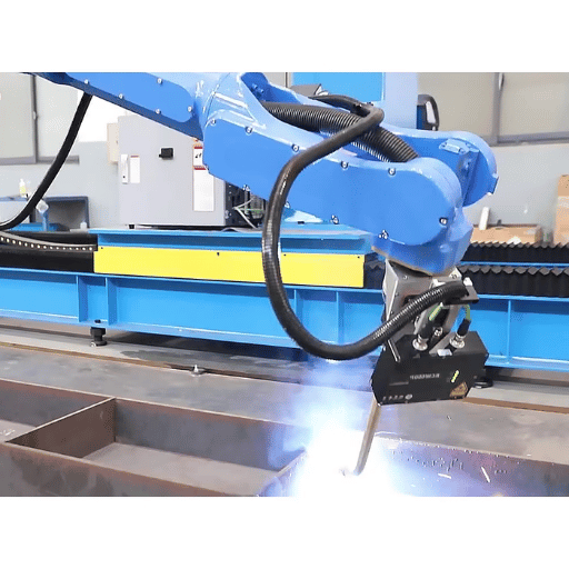
A7 axis cantilever robot adds a linear ground rail to a standard6-axis welding arm, extending its working envelope from a fixed point to a continuous 624meter zone. For steel structure fabricators welding long H-beams, box columns, roof beams – this extra axissimuplifies the process by removing the need to reposition workpieces or run multiple robots–processing one machine with the entire part length, reducing welding efficiency on long structural members. This deep dive examines how the system works, what the actual specs look like across manufacturers and how to decide whether buying a7th axisis a good investment for your shop.
Quick Specs: 7 Axis Cantilever Welding Robot
| Total Axes | 6 (robot arm) + 1 (ground rail) = 7 |
| Repeat Positioning Accuracy | ±0.05 mm (varies by manufacturer; some models ±0.1 mm) |
| Robot Payload | 6–12 kg (model dependent) |
| Arm Reach | 1,440–2,010 mm |
| Ground Rail Length | 6–24 m (customizable) |
| Welding Speed | Up to 5 m/min |
| Programming | Teaching-free (Tekla, SolidWorks, UG import) or teach pendant |
| Protection Rating | IP56 (J1–J2) / IP67 (J3–J6) |
What Is a 7 Axis Cantilever Robot?
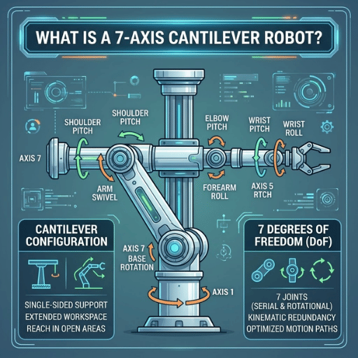
A 7 axis cantilever robot is an industrial welding system which mounts a 6-axis robot arm on a motorized ground rail — the 7th axis — using a cantilever (overhanging beam) structure. Its design permits the robot to be repositioned above and beside the workpiece, keeping the floor area directly below it open for overhead crane logistics.
In practice, “7-axis” causes confusion across the industry. A handful of manufacturers — such as OTC DAIHEN with its FD-V series — implement the 7th axis as a second rotational joint within the robot arm itself, opening up short interference points and other hard-to-reach areas. In a cantilever configuration, the 7th axis is always a linear ground-level rail which extends the robot’s working zone along the length of the workpiece. Both approaches address the same fundamental issue: providing more reach and flexibility than a fixed-pedestal 6-axis robot.
Structurally, the cantilever is the key difference from gantry-style welding systems. Gantry robots ride on overhead rails that run the full width and length of the work space and require heavy structural support and strong ceiling structures. A cantilever robot simply extends from one side, freeing up more floor space and easing integration into existing production lines where overhead crane access should not be blocked.
💡 Key Distinction
“7-axis robot”can be interpreted differently depending on the specifics. In cantilever welding systems, the7th axisisalways a ground-based linear rail; in articulated robotslikeOTC DAIHENs FD-V series, the7th axisis a second rotational joint in the arm itself.
How Does Teaching-Free Welding Technology Work?

Teaching-free welding replaces manual teach-pendant programming with automatic weld path generation. Operator-guided robot programming can take considerable time; a typical part requiring 175 individual seams can easily demand over 35 hours of manual teaching. With teaching-free software, the system imports the digital model, analyzes weld positions, and generates the full path in mere minutes.
Powered by AI vision and offline programming software, the process consists of three steps:
- 3D Design Import: The designer sends structural design files directly from Tekla Structures, SolidWorks, and UG (NX). CAD geometry, joint positions, and weld notes all get read in automatically.
- Vision-Based Seam Detection: A laser scanner (such as the CP350V laser tracker used in Zhouxiang systems) does intelligent line scan to locate the actual weld seam positions on the physical workpiece. This compensates for fabrication tolerances – the difference between the position indicated by the 3D model for a joint, and the actual position on the shop floor.
- automatic Path Generation: When the system locates the seam coordinates, it compares these to the welding process library and selects the appropriate parameters for wire feed speed, voltage, travel speed, and torch angle. From there, the robot performs the entire weld sequence without manual intervention.
Verbotics, a company that specializes in offline robot programming, claims their system decreased programming time for a 175-weld part from more than 35 hours (manual teaching) to just 1.5 hours. Across the industry, teaching-free systems provide a factor of 5-10x faster programming compared to traditional teach-pendant operation.
What Is a 7th Axis for Robots?
The 7 th axis in a cantilever welding robot is a motorized, ground-level rail that allows the entire robot body to travel along the length of the workpiece. Unlike the six joints of the robot arm (which control position and orientation of the welding torch), the 7 th axis provides translation – the ability to travel 6 to 24 meters along a straight track. Extending the working zone is the defining feature that makes single-robot coverage of long structural members possible. The ground rail employs a servo-driven rack-and-pinion or ball-screw system with synchronized motion control so the robot can weld continually while traveling along the rail without stopping to reposition.
⚠️ Common Misconception
Teaching-free does not mean zero setup time. workpiece positioning is still done by experienced operators because of fixture design, workpiece placement, and weld process parameter validation. What is eliminated is the hours of point-by-point path programming on the teach pendant – the most time-consuming, mindless part of the process.
Technical Specifications That Matter
Range of specs for 7 axis cantilever robots varies widely between manufacturers. Below is a comparison pulling data from two Zhouxiang models, plus the OTC DAIHEN FD-V6S, to show the market distribution.
| Parameter | Zhouxiang ZXR12-2010 | Zhouxiang ZXR10W-1440-D | OTC DAIHEN FD-V6S |
|---|---|---|---|
| Axes | 6 + ground rail | 6 + ground rail | 7 (integrated rotational) |
| Payload | 12 kg | 10 kg | 6 kg |
| Arm Reach | 2,010 mm | 1,440 mm | 1,427 mm |
| Repeat Accuracy | ±0.05 mm | ±0.05 mm | ±0.08 mm |
| Robot Weight | 313 kg | 210 kg | 145 kg |
| Protection (wrist) | IP67 | IP67 | IP67 |
| Power Capacity | 4.5 kVA | 4.5 kVA | 3.0 kVA |
| Wrist Design | Hollow (internal cable routing) | Hollow (internal cable routing) | Hollow |
📐 Engineering Note
IP67 on the wrist joints (J3-J6) is a must in welding applications. These joints operate closest to the arc and are exposed to weld spatter, grinding dust, and shielding gas residue. IP56 on the base joints (J1-J2) is sufficient because the cantilever mounting height keeps them clear of the welding zone spatter. All models must meet ISO 10218-1:2025, the revised international standard for weld-robot safety, which requires safety-rated monitored stop functions and operational mode.
Worth noting is the hollow wrist design. Internal cable routing eliminates the external cable bundle on older robots that wraps around the wrist. This prevents interference between the welding torch cable and the workpiece during complex motion paths – a common cause of unplanned stops and torch collisions on non-hollow-wrist systems.
7 Axis vs 6 Axis Welding Robot: What the Extra Axis Changes

A typical 6-axis welding robot bolted to a fixed pedestal has a working envelope defined by its arm reach — usually around 1,400 to 2,000 mm from the base. For any workpiece shorter than the arm reach, this works fine. When the workpiece extends beyond the robot’s reach though — say an 8-meter H-beam that needs fabricating — the 6-axis system hits a hard limit. The fabricator either has to reposition the workpiece using overhead cranes, add a second robot, or hook up a positioner to rotate the work into reach.
With a 7th axis ground rail, the story changes. A single robot traversing a 12-meter rail can weld the entire length of an 8-meter H-beam in one continuous operation, maintaining optimal torch angle throughout without manual repositioning stops.
✔ Advantages of the 7th Axis
- Covers 6–24 m working zone with a single robot
- Eliminates positioner equipment and reduces floor space
- Maintains optimal torch angle on long seams without interruption
- Avoids interference by repositioning the entire arm around obstacles
- Enables batch workpiece loading — crane carries multiple pieces onto the rail zone all at once, which can improve cycle time
⚠ Limitations
- Higher equipment cost (rail system, servo drives, additional cabling)
- Rail alignment and calibration need precision installation (±0.1 mm over full length)
- Ground rail maintenance: rack-and-pinion wear, rail cleaning, lubrication schedule
- Longer initial commissioning period vs fixed-mount installation
- Only linear motion does not provide the rotational dexterity of an integrated 7 th joint
“Seven-axis robots have the ability to lie down and reach around parts and obstacles. They are ideal for applications where part positioning is not available, and are able to hold optimal torch angle and attitude on longer parts without compromise.”
— Robots Done Right, Seven-Axis Welding Robots Technical Overview
A structural steel fabrication shop shows the difference clearly. Picture a facility processing 12-meter H-beams with fillet welds on both flanges. With a fixed 6-axis robot, each beam goes through at least two repositioning cycles — the crane hoists and turns the beam, the operator re-fixtures, and the robot re-calibrates its start point. Each cycle eats up 15 to 25 minutes of non-welding time. Now picture a 7 axis cantilever robot on a 15-meter rail. The beam gets placed once, and the robot welds the full length continuously. Across a shift of 20 beams, the repositioning savings alone recover 5–8 hours of productive welding time.
💡 The Workpiece Length Rule
If your typical workpiece is under 3 meters, a standard 6-axis robot with a positioner handles most applications just fine. Over 3 meters, manual repositioning becomes the production bottleneck — and the 7th axis starts paying for itself. This threshold is the core decision boundary between fixed-mount and cantilever configurations.
Applications: Where 7 Axis Cantilever Robots Excel

The cantilever welding robot best suits industries that build long, heavy steel parts with uniform weld patterns. Extended reach, teaching-free programming, and automatic seam identification make a strong combination for applications with lots of workpiece variation but standardized weld types.
| Industry | Typical Workpieces | Weld Types | Rail Length |
|---|---|---|---|
| Steel Structure Fabrication | H-beams, box columns, roof beams, gusset plates | Fillet, butt, multi-pass | 6–15 m |
| Shipbuilding | Hull sections, deck assemblies, bulkheads | Fillet, groove, tack | 12–24 m |
| Bridge Construction | Plate girders, cross-frames, splice plates | Butt, fillet, multi-pass | 8–15 m |
| Power Equipment | Boiler frames, pressure vessel supports, equipment platforms | Fillet, groove | 6–12 m |
Steel structure fabrication accounts for the largest share of cantilever robot deployments. Open-type components like H-beams with reinforcing plates, corbels, and purlin supports have standardized joint geometries that the teaching-free system handles with minimal operator input. Under the ISO 10218-2:2025 robot cell framework, these applications belong to the group of automated welding cells that require safety-rated monitored stop functions and defined operational zones.
Global robotic welding market growth confirms this trend. According to industry analysis, the market is expected to reach about USD20.78 billion by 2032, compared to USD10.66 billion in 2025, due to the deepening shortage of labor for skilled welding and the rising demand for automation in structural steel and shipbuilding. Within this market, cantilever configurations with teaching-free technology are among the fastest-growing segments, particularly in Asia-Pacific manufacturing hubs where the integration of digital twin systems and real-time data visualization is advancing production intelligence.
Some fabricators also integrate the cantilever robot welding workstation with upstream laser cutting machines, creating a cut-to-weld production line. Parts flow directly from cutting to the welding zone, reducing material handling steps — though this requires careful floor space planning and synchronized production scheduling.
How to Choose the Right 7 Axis Cantilever Robot for Your Workshop
Whether a 7 axis cantilever robot makes sense depends on a few measurable variables. Below is a framework mapping your production conditions to the right configuration.
Decision Framework: Configuration by Workpiece Length
- Workpiece length <3 m — A 6-axis robot with a standard positioner should be enough. Adding a 7th axis at this scale does not deliver proportional productivity gains.
- Workpiece length 3–8 m — 7 axis cantilever robot with a standard 6 m ground rail. This is the sweet spot where the extra axis removes repositioning and begins to pay for itself within 12–18 months.
- Workpiece length 8–15 m — 7 axis cantilever with extended rail (8–15 m). Ensure the foundation is level within ±0.1 mm per meter for rail alignment accuracy.
- Workpiece length >15 m — Consider an 8-axis or 9-axis gantry configuration, or dual cantilever robots working in tandem on a shared rail.
- Mixed workpiece sizes (variable production) — 7 axis cantilever with teaching-free software provides the greatest flexibility — each new part only requires a new 3D model file, not hours of reprogramming.
- ✔
Measure your maximum workpiece length — this single number determines whether the 7th axis is justified - ✔
Identify your weld types — fillet, butt, groove, multi-pass; confirm the robot and power source support all required processes - ✔
Check floor space and crane clearance — the cantilever extends from one side; verify the overhang does not obstruct existing crane paths - ✔
Evaluate programming needs — if you use Tekla Structures for steel detailing, teaching-free integration saves significant programming time - ✔
Consider dual-station layouts — while the robot welds on one side, operators load the next workpiece on the other side, maximizing arc-on time
For fabrication shops already using digital design workflows (Tekla, SolidWorks, or UG), the teaching-free capability is the deciding factor. Its software automatically generates welding paths from design models, so new products or design revisions do not require manual reprogramming. For shops still relying on manual drawings or 2D CAD, the teach-pendant approach still works — but without the speed advantage that justifies the 7th axis investment.
Would you like to taste a 7 axis cantilever robot for your production line?
View Cantilever Welding Robot Specifications →
Or request a free quote using your workpiece specifications with production volume.
Frequently Asked Questions
![7 Axis Cantilever Robot How It Works, Specs & Applications [2026]](https://zxweldingrobot.com/wp-content/uploads/2026/04/7-Axis-Cantilever-Robot-How-It-Works-Specs-Applications-2026-1.webp)
Q: How many axes does a cantilever welding robot have?
View Answer
A standard cantilever welding robot usually has 7 axes: 6 axes in the robot arm (base, shoulder, elbow, and 3 wrist joints) plus 1 linear ground rail axis. Some advanced configurations add an 8th axis (cantilever rotation) or 9th axis (workpiece positioner), but most cantilever welding workstations run on 7 coordinated axes.
Q: What is the difference between a cantilever and a gantry welding robot?
View Answer
A cantilever robot extends from one side on an overhanging beam, leaving the floor clear for crane access. A gantry robot runs on overhead rails across the whole working area, needing more structural support and ceiling height. Cantilever arrangements tend to fit better in older workshops with crane restrictions; gantry systems handle high-volume requirements in purpose-built facilities with very long or very wide workpieces.
Q: Can a 7 axis cantilever robot weld without manual programming?
View Answer
Yes, when the system has teaching-free software installed. It imports 3D models from Tekla, SolidWorks, or UG, then uses laser vision to scan the workpiece and automatically locate weld seam positions. From there, the software generates the complete weld path and process parameters without manual teach-pendant programming. Fixture setup and process parameter validation still require operator involvement.
Q: What workpiece size can a 7 axis cantilever robot handle?
View Answer
Maximum workpiece length is a function of the ground rail: most standard rails are between 6 and 15 meter, custom rails can be up to 24 meter. Workpiece width is limited by the overall cantilever overhang and arm reach (max 2.4 meter from the rail Centerline). Workpiece weight is a function of the floor or fixture capacity: not the robot, because the cantilever structure does not carry the workpiece load.
Q: How accurate is a 7 axis cantilever welding robot?
View Answer
Repeat positioning accuracy ranges from 0.05 mm to 0.1 mm using each manufacturer and the a-priori model. This applies to joints of the robot arm; the ground rail pile provides its own limit to repeat positioning accuracy (stated separately). For the welding applications, 0.1 mm repeat accuracy is acceptable for the majority of fillet and butt weld operations on structural steel.
Q: What file formats does teaching-free welding software support?
View Answer
Most teaching-free systems read IFC files from Tekla Structures and STEP/IGES files from SolidWorks. Some systems also accept native formats from Siemens NX (UG). DSTV (NC) files commonly used in the steel structure industry are supported by certain platforms as well. Check with the manufacturer whether their software reads your design platform’s native format or requires an intermediate export step.
About This Analysis
This guide was produced by the Zhouxiang engineering team, drawing on over 30 years of welding equipment manufacturing experience and deployments across 50+ countries. Specification data for Zhouxiang models reflects current production parameters. Third-party specifications (OTC DAIHEN) are sourced from publicly available product documentation. Market data is compiled from IFR and independent industry research firms. Where exact figures are unavailable, ranges are provided rather than estimated single values.
References & Sources
- ISO 10218-1:2025 — Robotics Safety Requirements for Industrial Robots — International Organization for Standardization
- ISO 10218-2:2025 — Safety Requirements for Industrial Robot Applications — International Organization for Standardization
- Real-Time Data Visualization of Welding Robot Data and Digital Twin Systems — PMC / National Institutes of Health
- 7-Axis Robots Product Overview — OTC DAIHEN
- Offline Robot Programming for Welding Automation — Verbotics
- Robotic Welding Market to Reach USD 20.78 Billion by 2032 — Kings Research
- 5 Common Failures in Robotic Welding and How to Prevent Them — Bernard & Tregaskiss
Related Articles
Reviewed by the Zhouxiang Engineering team Last update April 2026