Get in Touch with Zhouxiang
![8 Axis Cantilever Workstation: Complete Buyer's Guide [2026]](https://zxweldingrobot.com/wp-content/uploads/2026/04/1-5.webp)
Quick Specs: 8 A×is Cantilever Workstation
- Total A×es: 6 (robot) +1 (ground rail) +1 (Y-axis cross beam)
- Total Working Envelope: Customizable length up to 30+ meters 3.5 meter width 0.5 meter depth
- Welding Accuracy: ±0.1 mm with vision system
- Programming: Teach-free (Tekla, SolidWorks, UG import)
- Primary Use: Steel structure fabrication, bridge construction, shipbuilding
An 8 axis cantilever workstation is one of the most misunderstood categories in steel fabrication welding today. Bidders confuse it with 7-axis systems, over-specify 9-axis implementations that have more reach but no additional functionality, or omit it altogether because no bidder has explained what that eighth axis, exactly, does for the welding operation. Use this guide to understand the engineering, the selection calculus, and the trade-offs so you can evaluate your options.
What Is an 8-Axis Cantilever Welding Workstation?
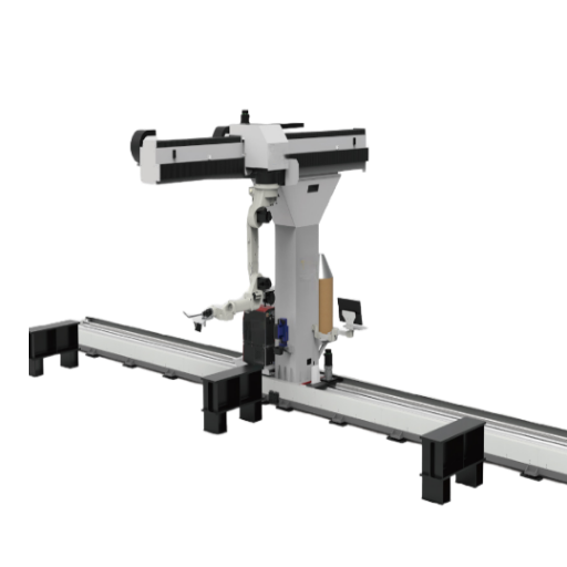
A cantilever welding workstation configures an industrial robot by placing it on a single-sided cantilever overhang arm, instead of a gantry frame. The “cantilever” leaves one side completely open, which makes it easy for an overhead crane to directly load workpieces onto the table in front of the robot without working around support columns.
In the 8 axis welding cell, two external axes are added to a standard 6 axis robot. Axis 7 is a linear ground rail that provides fullcoverage in the length direction. Axis 8 is a Y-axis cross beam that extends the robot out of the length (X) direction, leaving as much as 3.5 meters of workpiece width coverage. This width-direction flexibility is the feature that makes this system an eight-axis cantilever, compared to a seven-axis restriction of just forward and back robot traverse.
542,000
Industrial robots installed globally in 2024
320,500
New welders needed in the U.S. by 2029
$10.4B
Global robotic welding market (2025)
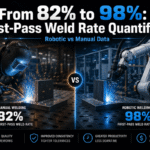
Numbers exhibit.. By the IFR 2025 World Robotics report, the world installed 542,000 industrial robots in 2024. The American Welding Society also projects that, just in the US, more than 320,500 new welders will be needed by 2029, as just over 157,000 will be retired away. These converging themes are driving steel structure fabricators, bridge builders, and shipyards toward smart welding workstation solutions that will keep production constant, while shrinking labor forces.
According to Precedence Research, the global robotic welding market reached $10.44 billion in 2025, projected to hit $26.94 billion by 2035. Cantilever configurations are taking a growing share of that market, especially among steel structure fabricators and bridge builders where long workpieces and direct overhead crane access are critical.
How the 8-Axis System Works — Axis-by-Axis Breakdown

Knowing what the various axes on the shop floor actually do is more important than attempting to learn what their various numbers mean. Every axis in an 8 axis welding robot affects the type of weld seam that can be achieved without repositioning workpieces, and how they interact to deliver that performance.
| Axis | Component | Function | Typical Range |
|---|---|---|---|
| 1 (Base) | Robot base rotation | Rotates entire arm assembly | ±165° |
| 2 (Shoulder) | Lower arm pivot | Lifts/lowers the arm | +80° / -135° |
| 3 (Elbow) | Upper arm pivot | Extends/retracts reach | +163° / -75° |
| 4-6 | Wrist (3 joints) | Torch orientation and angle control | ±180° / ±130° / ±360° |
| 7 (Rail) | Linear ground rail | X-axis travel along workpiece length | Customizable (up to 30 m+) |
| 8 (Beam) | Y-axis cross beam | Width-direction reach extension | 2 m effective (covers 3.5 m width) |
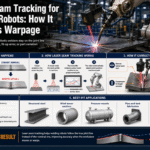
Beyond the axes themselves, a laser seam tracking system that dynamically tracks the true position of the weld joint and automatically adjusts the torch position during manufacturing. For higher accuracy robots are combined with a 3D vision system that captures the whole work piece and generates a point cloud model that is used by the control system to adapt the welding operation to the precise as-fabricated geometry of the joint rather than the original 3D model. With this visual system, positional accuracy of 0.1 mm can be achieved — a requirement for joint quality on high-precision steel structure assemblies.
Does an 8-Axis Cantilever Workstation Need Programming?
While traditional robot welding cells are hard-set and taught for each specific part, robotic cells are normally programmed via manual Pendent programming for every variation of part, taking from 4-8 hours for each different part. 8 axis cantilever cells use teach-free welding programs by importing the 3D part models into the system directly from Tekla, SolidWorks or UG. Once imported, the intelligent welding system identifies weld seams to be joined, determines the proper weld parameters from a built in expert library and generates the robot weld programs automatically. Operators with no previous experience on the robot are often taught in a day or two.
This is not a “tip of the iceberg” feature. For high-mix fabrication sources in 50 or more part variants a month, this can be the difference between a fully instrumented automation system which pays for itself or a robot sitting on the shelf waiting for a programmer to come by.
7-Axis vs 8-Axis vs 9-Axis Cantilever Workstation — Which Configuration Fits Your Production?

Number of axes of a cantilever welding robot defines its capability to reach the parts without moving the work piece. More axes means more capability but also higher cost and complexity. Your goal should not be buying the maximum capability, but matching the configuration to your actual workpieces.
| Parameter | 7-Axis | 8-Axis | 9-Axis |
|---|---|---|---|
| External Axes | Ground rail only | Ground rail + Y-axis beam | Rail + beam + positioner |
| Max Workpiece Width | ≤3.0 m | Up to 3.5 m | 3.5 m + rotation |
| Weld Positions | Flat, horizontal | Flat, horizontal | Flat, vertical, overhead |
| Seam Types | Straight, arc | Straight, arc, curved | All + circumferential |
| Best For | Simple long beams | Wide plates, diaphragms | Cylindrical/rotating parts |
| Relative Cost | Lowest | Mid-range | Highest |
The Width Rule: Workpiece Cross-Section Determines Your Axis Count
- Workpiece 3.0 m wide and only straight/arc seams allowed 7-axis cantilever
- Workpiece width 3.0-3.5 m or mixed flat/vertical fillet welds 8-axis cantilever
- Workpiece requires rotation for circumferential / multi-pass welds 9-axis cantilever
- Workpiece mass higher than cantilever load or necessaress bilateral entrance concider gantry welding robot
⚠️ Common Mistake
The 9 axis system for flat plate assemblies. Where you just have flat, horizontal welds. A positioner sits unused in that scenario, and the extra axis makes the control system more complicated for no benefit.
For most steel fabrications, H-beams, box columns, diaphragms – the 8 axis system is the solution.
For a detailed comparison of all three mounting architectures, see our guide to ground rail vs cantilever vs gantry welding robots. If your main parts are short, small parts as opposed to long, center beam parts then you may prefer a ground rail welding robot station.
What to Evaluate in an 8-Axis Cantilever Welding System
Not all smart welding workstations make sense. A system that operates three shifts a day and one that is sitting on a shelf collecting dust are two different animals and are often decided by six criteria that buyers look for—and ignore:
1. Robot body and reach. Select a hollow-wrist industrial robot with integrated cable management. This allows cable control during complex torch Z-movements. Repeat positioning precision should be 0.05 mm or better. Reach options are typically 1,440–2,010 mm according to workpiece size.
2. Welding machine, power supply. Digital inverter welding power supply (MIG/MAG) is standard for heavy steel structure fabrication. Ask if system is capable of switching TIG welding process for stainless steel and aluminum jobs. Inverter power supplies keep arc parameters steady through continuous duty cycles without drift.
3. Vision system – the value-added feature. At minimum, look for a 2D laser seam tracking system, which continuously adjusts deviations as the part is being welded in real time. Top-rated technology is a 3D vision system which performs a pre-weld scan of the actual workpiece and compiles a point cloud model–important because fabricated steel is not a machined part, so spot-to-spot variation always occurs due to thermal warpage, fit-up gaps and plasma-cut edges.
“The vision system is the most critical feature separating a reliably functional cantilever workstation from one constantly tripped-up by part variation. If you can’t provide a 3D scan, you are relying on perfect fixturing–and in steel fabrication, nothing is perfect.”
— Welding Automation Engineer, based on industry deployment observations
4. Ground rail and Y-axis beam. Choose the length of rail track to accommodate your longest workpieces. Confirm it features automation of lubrication system–manual lubrication is always a forgotten maintenance task. Standard workstations have 2 meters of Y-axis travel, suitable for parts up to 3.5 meters wide.
5. Torch and gun cleaning station. A water-cooled welding gun prolongs gun life in heavy-duty operations. Automatic gun cleaning with wire cutting and anti-spatter spray is a necessity on automatic welding systems- the gun nozzle wears down from spatter build-up if not automatically cleaned. Verify if nozzle maintenance is automatic or hand operated between shifts.
6. Software and control system integration. Teach-free welding software should take models produced in Tekla, SolidWorks and UG directly without file translation. Digital twin providing remote control and monitoring is preferred. Confirm TCP/IP or EtherCAT communication protocol if your facility subscribes to MES (Manufacturing Execution System).
For ongoing upkeep considerations, see our detailed guide on welding robot maintenance schedules, costs, and best practices.
Where 8-Axis Cantilever Workstations Are Deployed — Industry Applications

Cantilever robot workstations see the heaviest deployment in steel structure fabrication, bridge erection component manufacturing, ship assembly, and large machinery frame production. Common denominators across these industries: elongated workpieces, continuous high-quality welds, and the impossibility of manual welding to match automated quality across shifts.
| Industry | Typical Workpieces | Why 8-Axis Cantilever |
|---|---|---|
| Steel Structure Fabrication | H-beams, box columns, plate assemblies, stiffeners | Long seams + wide cross-section (3–3.5 m) |
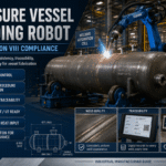
| Bridge Construction | Diaphragm plates, girders, bridge deck panels | Multi-pass fillet welds, EN 1090 compliance |
| Shipbuilding | Hull panels, bulkheads, structural frames | Welding for bridge and ship plate unit structures |
| Heavy Machinery | Crane booms, gantry frames, chassis modules | Complex welding joints requiring multi-position access |
Imagine a steel erection shop that has a dedicated bridge diaphragm plates manufacturing facility—panels 10 meters long by 3.2 meters wide, with 400 mm intervals between vertical stiffener rib fillet welds. With manual arc welding, three welders 8 hours could install one panel of welding. In a typical shop shift, that configuration would lose about 30% of its time to checking contours, adjusting torch angle, and taking 15-minute breaks mandated by ergonomics regulations. An 8 axis cantilever workstation performing the same production run needs one user and still completes in only about 3 hours. Y-axis travel eliminates the repositioning overhead entirely, and automatic welding parameters remain locked throughout the entire run. Those are the kind of throughput improvements that about why the superiority of the cantilever type configuration is becoming less, not more, apparent as we run out of skilled welders.
Yet safety compliance adds just one more nuance to consider. Fully documented safety compliance for welding cells built at ISO 10218-1:2025 and ISO 10218-2:2025 can only be achieved in robotic workstations. Recent re-visions of ISO 10218 standards make functional safety requirements within compliance documentation more transparent, a trend Robotics247 reports is driven by an effort to create clearer accountability in the decision to automate.
How Much Does an 8-Axis Cantilever Welding Workstation Cost?
Cost depends on configuration—source brand, rail length, vision system sophistication, and options like gun cleaning, dust collection, etc. Entry level robotic welding cells as single-robot, basic seam tracking units sell for around $25,000-$80,000 equipment figure for the robot arm and welding source (if not other welding hardware). Synchronous 8-axis cantilever work stations with software that does not require teach-in, 3D vision, and ground rails 10–15 meters long sell at a higher price point more depending on vendor and configuration. To learn how much the welding robot is going to cost in 2026, see our analysis of what a welding robot actually costs in 2026. For most shops, payback is within 12 to 24 months for displaced labor and throughput improvements.
How to Select the Right 8-Axis Cantilever Workstation for Your Shop
Purchasing a robotic welding workstation is different than buying a welding machine. The welding equipment is only one portion of the system: fixturing, programming, material handling, training, and ongoing support are all integral parts of the total cost. In fact, some robotic welding systems end up sitting idle within 6 months of installation. It is not the technology itself failing — it is because the selection process was incomplete.
- ✔
Map your workpiece portfolio. Measure the maximum length, width, and height across all part families you intend to weld. This determines rail length and whether the Y-axis beam (8-axis) or a rotary positioner (9-axis) is necessary. - ✔
Define seam types and weld positions. Flat fillet welds? Vertical? Circumferential? The seam map determines the minimum axis count and whether a positioner is needed. - ✔
Calculate throughput targets. Parts per shift, shifts per day. This determines whether a single-station layout or a dual A-B station configuration (where the operator loads one side while the robot welds the other) is justified. - ✔
Evaluate integration constraints. Available floor space, crane hook height, electrical supply capacity, fume extraction requirements, and communication protocols if MES integration is planned. The track length can be customized, but ceiling height and floor flatness are fixed. - ✔
Request a demo weld on your actual workpiece. Any serious manufacturer will weld your sample part before you commit. If they skip the application review, they are selling equipment, not a solution.
Still have problems getting the outsourcing step right? Here’s what can go wrong when you skip step five. A Midwestern job shop bought a robotic welding cell and assumed their existing parts would be suitable for automation without a formal application review. They had to redesign fixturing in process because what they first put together was not going to repeat in the robot’s tolerance window. System sat for weeks while they refined fixturing to be more repeatable. Lesson: regard fixtures as a component of the entire weld cell toolset, rather than keeping them as an afterthought. For the best weld quality, robotic systems need consistent fixturing.
💡 Pro Tip
Begin with only one part family of high impact parts. Nail down the welding quality, cycle time and operator flow on just that one product before attempting others. Automating 10 part families on day 1 is one of the top reasons welding robot projects stall. One proven simple cell building that confidence before complicating the operation.
Ready to match a configuration to your workpieces?
Try our interactive free tools or speak to an engineer direct.
Frequently Asked Questions

Q: What is the maximum working range of an 8-axis cantilever workstation?
View Answer
Standard, the cells can process workpieces as long as 12 meters, 3.5 meters wide and 0.5 meters deep. Ground rail track length can be configured well beyond 12 m — some bridge fabrication systems run 30 m or more. Effective travel on the Y axis is 2m which leaves the robot arm sufficient lateral stretch to reach across a 3.5 meter workpiece over a single cantilever pass.
Q: Can an 8-axis cantilever workstation handle MIG and TIG welding?
View Answer
Standard, with MIG/MAG welding with CO2 or argon/CO2 mixed shielding gas this configuration works for carbon steel / structural steel welding applications. TIG welding option can be specified for work with stainless or aluminum material, but will require a different torch setup and power source configuration. Coordinate your material mix with the manufacturer during the quoting process.
Q: What welding positions can an 8-axis cantilever system reach?
View Answer
Flat and horizontal weld positions are well within reach for an 8-axis setup. Vertical and overhead positions generally call for a 9-axis system with a rotary positioner that turns the workpiece into a flat welding orientation.
Q: How long does it take to set up a new workpiece on a teach-free system?
View Answer
With teach-free off-line programming that imports CAD models, setting up the cell for a new part variant takes minutes not the 4-8 hours typical of pendant teaching. Software imports a 3D model file, identifies all weld seams, and auto-generates the robot program. After the operator confirms parameters, the cycle launches. This can be managed by operators without any prior robotics programming experience.
Q: What maintenance does an 8-axis cantilever workstation require?
View Answer
Clean the torch nozzle and check that the wire feed is working each day (5 10 minutes). Check wire gas and cable routing every week (15 20 minutes). Calibrate the tools, check the safety interlock systems monthly (30 45 minutes). Grease the robot joints, check rail bearings and Y axis beam bearings and check reducer backlash quarterly (1 2 hours). Re-calibrate robot and update controller firmware and check safety systems annually (4 6 hours). Industry-wide, the single most overlooked maintenance task is the torch liner a worn liner causes wire blocking resistance, arc fluctuations and porosity often blamed on the robot.
Q: Is an 8-axis cantilever workstation suitable for small-batch production?
View Answer
Work in batches even as small as 10 20 identical parts can work well in a teach-free system. Traditional robot cells required time consuming programming per part tooling changeover, discouraging small batch size processing. Model-based teach-free systems remove that inefficiency – few minute changeover times mean minimal programming costs for any batch size. Break-even point varies depending on labor cost and weld complexity but makers of small lot, high mix parts increasingly cite teachfree cantilever systems as cost effective.
References & Sources
- IFR World Robotics 2025 — Industrial Robots Executive Summary — International Federation of Robotics
- Welding Workforce Data — U.S. Demand Projections — American Welding Society
- Robotic Welding Market Size & Forecast 2025–2035 — Precedence Research
- ISO 10218-1:2025 — Robotics Safety Requirements — International Organization for Standardization
- A3 Revises ISO 10218 Robot Safety Standards for 2025 — Robotics247
- Why Do Some Robotic Welding Projects Fail? – KC Robotics
About This Analysis
This guide was written by the Zhouxiang engineering content team, based on 30 years of manufacturing welding equipment experience and more than 1,000 robotic welding workstation deployments in the steel structure, shipbuilding, bridge, power equipment industry. Axis configuration and teach-free programming details are drawn from our ZX cantilever welding robot product line, with market data based on IFR and AWS.public data, and a buyer’s error based on information from industry people, such as CLOOS North America and KC Robotics.